 Embedded HandbookApps
99. Motion: MPU-6050 and ADXL345
An accelerometer measures acceleration together with gravity, a gyroscope measures angular rate. From the first, at rest, you get tilt; from the second, by integration, an angle that drifts over time. The MPU-6050 carries both sensors, the ADXL345 only an accelerometer. These two chips show everything people trip over: a sensor that sleeps after power-up, two different byte orders, the gyroscope's zero offset, and a filter that builds one good measurement out of two bad ones.
I²C connection is in sections 17 and 95.
Terms used in the documentation
Term Meaning accelerometer measures acceleration plus gravity gyroscope, angular rate measures rotation speed IMU (inertial measurement unit) an accelerometer and gyroscope in one module full-scale range the measurement range sensitivity, LSB/g code units per g pitch, roll, yaw rotation about the three axes zero-rate offset, bias the gyroscope's zero offset drift slow creep of the angle complementary filter combines a fast and a slow source big-endian, little-endian most significant byte first, least significant byte first
99.1 What they measure
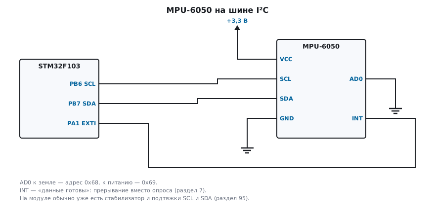
- The accelerometer measures the sum of gravity and acceleration. At rest only gravity remains, and its direction shows how the board is tilted: pitch and roll. A rotation about the vertical — yaw — does not change the gravity vector, and the accelerometer does not see it.
- The gyroscope measures angular rate. The angle is its integral, and any zero offset accumulates: 0.5 °/s over a minute is 30 degrees.
| MPU-6050 | ADXL345 | |
|---|---|---|
| measures | acceleration and angular rate, on three axes | acceleration on three axes |
| I²C address | 0x68 or 0x69 — set by the AD0 pin | 0x53 or 0x1D — set by the ALT ADDRESS pin |
| model code | 0x68 in register 0x75 | 0xE5 in register 0x00 |
| byte order | most significant first | least significant first |
| after power-up | sleeps | standby: bit 3 of register 0x2D enables measurement |
99.2 Scales
The range is set by two bits in registers 0x1C (acceleration) and 0x1B (angular rate), and it determines how many code units correspond to one unit of the quantity:
| AFS_SEL | Acceleration | Code units per g |
|---|---|---|
| 0 | ±2 g | 16384 |
| 1 | ±4 g | 8192 |
| 2 | ±8 g | 4096 |
| 3 | ±16 g | 2048 |
| FS_SEL | Angular rate | Code units per °/s |
|---|---|---|
| 0 | ±250 °/s | 131 |
| 1 | ±500 °/s | 65.5 |
| 2 | ±1000 °/s | 32.8 |
| 3 | ±2000 °/s | 16.4 |
On the ADXL345 in full-resolution mode the step is 3.9 thousandths of a g per code unit, about 256 units per g at any range.
#define MPU_LSB_PER_G(afs) (16384u >> (afs))
static const uint16_t mpu_lsb_per_dps_x10[4] = { 1310, 655, 328, 164 };
A narrow range is more precise, a wide one does not saturate: ±2 g is enough for tilt, an impact needs ±16 g.
99.3 MPU-6050: wake it up and read it
After power-up the MPU-6050 sleeps and holds zeros in its data registers. Startup is:
check the model code, write 0 to PWR_MGMT_1 (the documentation recommends
0x01 right away — the clock from the gyroscope oscillator, which is more stable than the internal 8 MHz)
and select the ranges. Code 0x68 is returned only by the MPU-6050: modules sold under the same
name with an MPU-6500 or MPU-9250 answer 0x70 and 0x71, and mpu_init will reject them;
the read is 14 bytes from 0x3B in one transaction: three accelerations, temperature, three
rates, each value most significant byte first:
int mpu_init(unsigned afs, unsigned fs)
{
    uint8_t id = 0;
    if (!i2c_read(MPU_ADDR, MPU_WHO_AM_I, &id, 1) || id != 0x68u)
        return 0;                       /* нет ответа или это не MPU-6050 */
    i2c_write_reg(MPU_ADDR, MPU_PWR_MGMT_1, 0x00u);     /* разбудить: после включения он спит */
    i2c_write_reg(MPU_ADDR, MPU_ACCEL_CONFIG, (uint8_t)(afs << 3));
    i2c_write_reg(MPU_ADDR, MPU_GYRO_CONFIG, (uint8_t)(fs << 3));
    return 1;
}

void mpu_parse(const uint8_t b[14], mpu_raw_t *r)
{
    r->ax = be16(b);
    r->ay = be16(b + 2);
    r->az = be16(b + 4);
    r->temp = be16(b + 6);
    r->gx = be16(b + 8);
    r->gy = be16(b + 10);
    r->gz = be16(b + 12);
}

int32_t mpu_temp_c100(int16_t raw)
{
    return (int32_t)raw * 100 / 340 + 3653;
}
i2c_read and i2c_write_reg are the bus functions from section 17. On the PC
a model of the sensor's registers replaces the bus: before mpu_init a read returns zeros,
after it — codes 8192, 0, 14189, −1500, 131, −262 and 0. At ±2 g this is 0.5 g
on X and 0.866 g on Z; the temperature is 32.12 °C (this is the die temperature,
not the air); the angular rates are 1.00 and −2.00 °/s.
99.4 ADXL345: the same parsing in reverse
The ADXL345 has six bytes from 0x32, and for each value the least significant byte comes first:
void adxl_parse(const uint8_t b[6], int16_t a[3])
{
    a[0] = le16(b);
    a[1] = le16(b + 2);
    a[2] = le16(b + 4);
}
The bytes 00 01 00 00 FF 00 are X = 256 and Z = 255, about 1 g. Parsed
"as on the MPU-6050", most significant byte first, they give X = 1 and Z = −256 —
plausible numbers with not a drop of meaning. You cannot see this mistake
in the schematic or by a missing reply: the sensor answers, the numbers change,
but wrongly.
99.5 Tilt from the accelerometer
At rest the acceleration vector is gravity, and the angles come from its projections:
void tilt_deg(float ax, float ay, float az, float *pitch, float *roll)
{
    *pitch = atan2f(-ax, sqrtf(ay * ay + az * az)) * 57.29578f;
    *roll = atan2f(ay, az) * 57.29578f;
}
0.5 g on X and 0.866 g on Z is pitch −30.00° and roll 0.00°. This works only at rest or in uniform motion: any acceleration tilts the vector, and in a shaking device such a tilt reading jumps.
99.6 Gyroscope: zero and drift
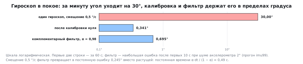
At rest a gyroscope shows not zero but its offset, and under integration it accumulates. The model: the board is still, the gyroscope shows an offset of 0.5 °/s, samples 100 times per second. After 60 s the gyroscope angle has drifted by 30.00°.
The first remedy is zero calibration: average the samples at rest and then subtract the average:
float gyro_bias(const int16_t *raw, unsigned n, unsigned fs)
{
    int32_t sum = 0;
    for (unsigned i = 0; i < n; i++)
        sum += raw[i];
    return sum * 10.0f / ((float)n * mpu_lsb_per_dps_x10[fs]);
}
From 200 noisy samples the model estimated the offset at 0.498 °/s (actually 0.504), and after subtraction the angle drifted by 0.341° over the same 60 s instead of 30 (more precisely, 30.2°: in this model the offset is set as an integer code — 0.5 × 131 = 65.5 rounded to 66, that is 0.504 °/s). But the offset wanders with temperature, so one calibration at power-up is not enough — you need a second source of the angle.
99.7 Complementary filter
You can trust the gyroscope over a short interval and the accelerometer over a long one. The complementary filter does exactly that: it adds the rotation from the gyroscope to the angle and pulls the result slightly toward the angle from the accelerometer:
float comp_step(float angle, float gyro_dps, float acc_deg, float dt, float alpha)
{
    return alpha * (angle + gyro_dps * dt) + (1.0f - alpha) * acc_deg;
}
With α = 0.98 and a step of 0.01 s the time constant α·dt / (1 − α) = 0.49 s: whatever changes faster comes from the gyroscope, slower — from the accelerometer. The gyroscope offset now gives not a growing but a constant error — only 0.245°. The model: the board is still at 10°, the gyroscope has an offset of 0.5 °/s, the accelerometer has noise with a spread of 2°. After the first 10 s the filter error did not exceed 0.695°, while the angle from the gyroscope alone drifted by 30.00° over the same time.
99.8 Pitfalls
The MPU-6050 returns only zeros. It sleeps after power-up. Write 0
to PWR_MGMT_1 (0x6B).
The ADXL345 returns zeros. Measurement is not enabled — bit 3 of register 0x2D.
ADXL345 readings are garbage with a correct circuit. Byte order: the ADXL345 is least significant first, the MPU-6050 is most significant first.
The gyroscope angle drifts by tens of degrees per minute. The zero offset is being integrated. Calibrate the zero at rest and correct with the accelerometer.
Tilt from the accelerometer jumps during motion. The accelerometer measures more than gravity. You need a filter together with the gyroscope.
The MPU-6050 temperature is above room temperature. It is the die temperature, not the air.
Yaw from the accelerometer does not work. A rotation about the vertical does not change the gravity vector. You need a magnetometer.
99.9 Summary
- At rest the accelerometer shows gravity — hence pitch and roll; yaw it does not see.
- The gyroscope gives angular rate; the angle is the integral, and an offset of 0.5 °/s adds up to 30.00° over a minute.
- The MPU-6050 sleeps after power-up, the ADXL345 is in standby: both must be enabled.
- Byte order: the MPU-6050 is most significant first, the ADXL345 is least significant first.
- Zero calibration at rest cuts the drift from 30 degrees to 0.341° per minute, but the offset wanders with temperature.
- A complementary filter with α = 0.98 at 100 Hz has a time constant of 0.49 s; the gyroscope offset gives a constant error of 0.245° instead of a growing one.
Next: section 99а "A flight controller on STM32: inside Betaflight — 8 kHz gyro, filters, PID and DShot" — the same gyroscope, but over SPI at 8 kHz: filters against motor noise, the angular rate controller and the DShot digital motor protocol.