 Embedded HandbookApps
99а. A flight controller on STM32: inside Betaflight — 8 kHz gyro, filters, PID and DShot
In section 99 the MPU-6050 was read over I²C a hundred times a second, and the angle was built with a complementary filter. That is not enough for a racing quadcopter: the gyro is polled over SPI eight thousand times a second, motor noise is cleaned out of its signal, the controller holds the angular rate, and the throttle goes to the electronic speed controllers as a digital frame. All of this is done by Betaflight — open-source firmware for flight controllers on STM32. Here it is taken apart by its code: which microcontrollers, how the gyro is read, which filters and in what order, what the controller computes and how the DShot protocol works. The key functions were built on a PC and run against a model of the gyro and the motor.
Sources: Betaflight 2026.12.0-alpha (commit 744f95f):
src/main/common/filter.c, sdft.c, src/main/sensors/gyro.c,
gyro_init.c, gyro_filter_impl.c, src/main/flight/dyn_notch_filter.c,
rpm_filter.c, pid.c, pid.h, pid_init.c, mixer_init.c,
src/main/drivers/dshot.c, accgyro/gyro_sync.c, accgyro/accgyro_mpu.c,
src/main/config/config.c, src/main/pg/*.c,
src/platform/common/stm32/dshot_dpwm.c, pwm_output_dshot_shared.c,
src/platform/STM32/pwm_output_dshot.c. filter.c, maths.c, sdft.c,
dyn_notch_filter.c and rpm_filter.c were built with gcc on a PC without changes;
prepareDshotPacket, the telemetry decoding and the DMA buffer fill were cut from
the files verbatim. The model of the gyro, the motors and the ESC is our own.
The run is _verify/bf99a/bf99a.py, the log is _verify/bf99a/bf99a_host.txt.
License: Betaflight is GPL-3.0 (file LICENSE; the file headers say "either
version 3, or any later version"); this section gives a retelling and short
quotes with paths.
Terms used in the documentation
Term Meaning flight controller (FC) the board that flies the aircraft ESC (electronic speed controller) the motor speed controller looptime, pid_process_denomloop period, divider of the controller rate PT1, PT2, PT3 lowpass lowpass filter of order 1, 2 and 3 SVF (state variable filter), in the CLI — BIQUAD a filter built on state variables notch filter a filter that cuts a narrow band dynamic notch, SDFT a notch that tracks peaks, sliding DFT RPM filter a filter tuned by motor speed bidirectional DShot, eRPM DShot with a reply from the ESC, electrical RPM GCR (group coded recording) 4-bit → 5-bit code in the ESC reply feedforward, I-term relax, anti-gravity feedforward, I-term relaxation, "anti-gravity" burst DMA ( DMAR), bitbangtimer burst DMA, output through a GPIO port
99а.1 What is inside and what it runs on
src/platform/STM32/startup/ holds startup files for STM32F405, F411,
F446, F722, F745, F746, F765, G474, H562, H563, H723, H730, H735, H743, H757,
H7A3, C562, C591, C5A3 and N657. Next to STM32 there are the directories AT32,
APM32, ESP32, PICO, X32 and SIMULATOR — the firmware core is shared.
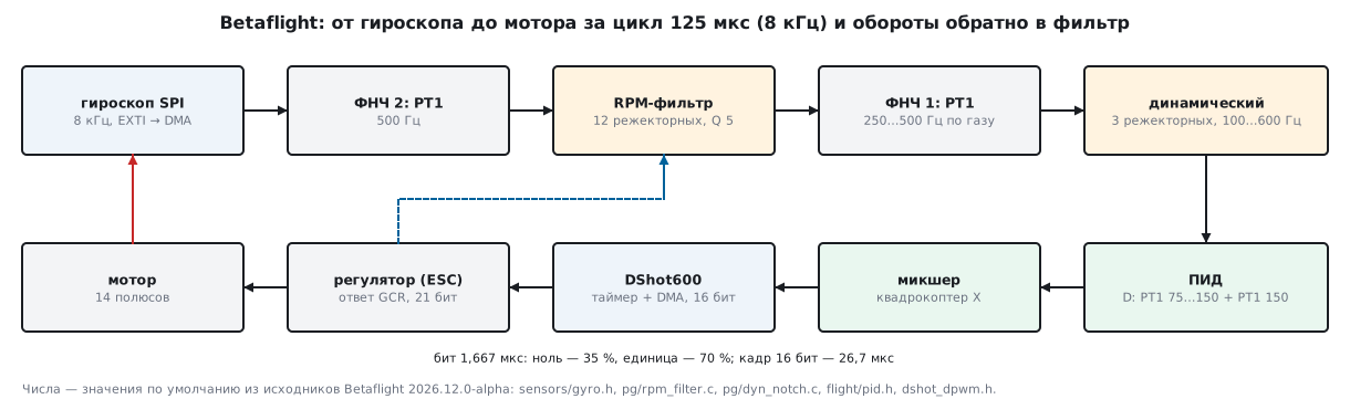
One loop goes like this (fc/core.c, sensors/gyro.c): the filtering task
decodes the DShot telemetry and runs the gyro through the filters, then
the main task computes the controller (subTaskPidController) and sends the throttle
to the motors (subTaskMotorUpdate). The RPM that the ESCs send
back tunes the filter in the next loop.
The firmware for F405 was built with make STM32F405 in stm-arm:1: 649573
bytes of flash out of 992 KB (63.95 %), 107820 bytes of RAM out of 128 KB and 13388 bytes
of CCM. The largest function of the loop is pidController, 5812 bytes;
rpmFilterRun is 840, pt1FilterApply is 26. That image has gcc 12.2.1, while Betaflight
requires 13.3.1: the version check had to be removed, and in the copy : uint8_t
was taken out of typedef enum : uint8_t (C23 syntax in rx/expresslrs_common.h).
99а.2 The gyro: SPI, 8 kHz, interrupt and DMA
The drivers are in src/main/drivers/accgyro/. The most common on boards:
accgyro_spi_mpu6000.c (SPI no faster than 20 MHz), accgyro_spi_icm426xx.c
(ICM-42688P and relatives, up to 24 MHz, output data rate 8 kHz — code 3 in the table
odrLUT) and accgyro_spi_bmi270.c (up to 10 MHz). The sampling rate is set by
gyroSetSampleRate in gyro_sync.c: 8000 Hz by default, 3200 for the BMI270 and BMI160,
6400 for the ICM-45686, 9000 for the ICM-20649.
Polling is not driven by a timer. The gyro's "data ready" pin goes to EXTI;
the handler mpuIntExtiHandler (accgyro_mpu.c) immediately starts a chain of
SPI transfers over DMA — the address of the first register with the read bit | 0x80,
then acceleration, temperature and gyro in one piece (on the MPU-6000 the read
starts at the acceleration register). The CPU learns about the data when it is
already in memory.
The loop period is targetLooptime = pid_process_denom × 10⁶ / rate:
125 µs at 8 kHz with divider 1 (by default DEFAULT_PID_PROCESS_DENOM
is 1). config.c raises the divider if the motor output cannot keep up with the loop.
This rule recomputed for three cases:
| Board and setting | Protocol | Divider | PID rate |
|---|---|---|---|
| F405, 168 MHz, bidirectional DShot600 | DShot300 | 2 | 4 kHz |
| F722, bidirectional DShot600 | DShot600 | 1 | 8 kHz |
| F722, bidirectional DShot300 | DShot300 | 2 | 4 kHz |
On F405 (USE_PID_DENOM_CHECK in target.h), with bidirectional DShot and
overclocking below level 2, the protocol silently changes to DShot300, and with a gyro
faster than 4 kHz the divider becomes at least 2. The margin for the motor output comes from
config.c: 100 µs for DShot300 and 31.25 µs for DShot600, and with telemetry —
twice as much.
99а.3 Lowpass filters: PT1, PT2, PT3 and SVF
The main building block is PT1, a first-order stage (common/filter.c):
FAST_CODE_NOINLINE float pt1FilterGain(float f_cut, float dT)
{
    float omega = 2.0f * M_PIf * f_cut * dT;
    return omega / (omega + 1.0f);
}
FAST_CODE float pt1FilterApply(pt1Filter_t *filter, float input)
{
    filter->state = filter->state + filter->k * (input - filter->state);
    return filter->state;
}
At 250 Hz and a step of 125 µs the gain is 0.164124. PT2 and PT3 are two and three such stages in a row; to get −3 dB at the cutoff frequency, the frequency is multiplied by 1.553773974 and 1.961459177. The fourth type is SVF, a second-order Butterworth filter on state variables. Measured with the real functions at 8 kHz, cutoff 250 Hz:
| Filter | 100 Hz | 250 Hz | 500 Hz | 1000 Hz | Delay at 10 Hz |
|---|---|---|---|---|---|
| PT1 | −0.76 dB | −3.41 dB | −7.58 dB | −12.83 dB | 0.636 ms |
| PT2 | −0.72 dB | −3.74 dB | −9.92 dB | −19.29 dB | 0.819 ms |
| PT3 | −0.73 dB | −4.00 dB | −11.52 dB | −24.33 dB | 0.973 ms |
| SVF | −0.11 dB | −3.01 dB | −12.46 dB | −24.97 dB | 0.898 ms |
PT1 gives −3.41 dB at the cutoff, not −3 dB: the gain formula is an approximation. SVF cuts hardest of all above the cutoff and barely touches the band below it.
By default (sensors/gyro.h, gyro.c) the gyro passes through two PT1 stages. LPF 2 —
500 Hz — runs at the gyro rate before decimation. LPF 1 is dynamic:
its cutoff rises with throttle from 250 to 500 Hz (dynLpfCutoffFreq, curve expo 5): at throttle
0.25 it is 335.9 Hz, at 0.5 it is 406.2 Hz. The D term has its own two PT1 stages:
a dynamic one from 75 to 150 Hz and a fixed one at 150 Hz. The price of filters is delay:
| Chain | 100 Hz | 200 Hz | 400 Hz | Delay at 10 Hz |
|---|---|---|---|---|
| gyro: PT1 250 + PT1 500 | −1.00 dB | −3.34 dB | −8.81 dB | 0.954 ms |
| D: PT1 75 + PT1 150 | −6.35 dB | −14.05 dB | −24.38 dB | 3.168 ms |
How FIR and IIR filters work is covered in section 81а.
99а.4 Notch filters: the RPM filter and the dynamic one
The order in gyro_filter_impl.c: decimation (with LPF 2), RPM filter, two
static notches (off by default — frequency 0), LPF 1,
dynamic notch. All the notches are the same SVF in notch
configuration. Measured at 300 Hz:
| Q factor | 300 Hz | 285 Hz | 315 Hz | 250 Hz | 350 Hz | 100 Hz | Delay at 10 Hz |
|---|---|---|---|---|---|---|---|
| Q 5 (RPM filter) | −86.29 dB | −6.75 dB | −7.09 dB | −1.12 dB | −1.49 dB | −0.02 dB | 0.1057 ms |
| Q 3 (dynamic) | −90.74 dB | −10.56 dB | −10.95 dB | −2.59 dB | −3.29 dB | −0.07 dB | 0.1762 ms |
The RPM filter (flight/rpm_filter.c, settings in pg/rpm_filter.c) puts
a notch on each of the three harmonics of each motor: 12 per axis on
a quadcopter, Q 5 (500 / 100), lower limit 100 Hz, below 150 Hz
the weight fades out smoothly (a 50 Hz band), the upper limit is 0.48 of the loop rate, 3840 Hz.
2 notches are updated per loop: all 12 in 1 ms. The frequencies come from
DShot telemetry (99а.6); without it the filter is off.
Model: motion at 10 Hz with a swing of 50 °/s, four motors at 330, 335, 340
and 345 rev/s with harmonics of 8, 4 and 2 °/s, noise ±2 °/s. After the real
rpmFilterRun, motor 1's harmonics at 330, 660 and 990 Hz dropped from 7.993,
4.017 and 2.018 to 0.0008, 0.0003 and 0.0002 (−79.7, −82.9, −78.4 dB); for
motor 4 — by −81.0, −84.8 and −77.2 dB. The 10 Hz motion: 49.98 before and after.
A motor at 120 Hz — weight (120 − 100) / 50 = 0.4 — is damped only weakly: 8.000 → 0.990.
The dynamic notch (dyn_notch_filter.c, common/sdft.c) looks for
what is not tied to motor speed — frame resonances. A sliding DFT over 72
samples gives 36 bins. At 8 kHz with an upper limit of 600 Hz, groups of
6 samples are averaged, the DFT runs at 1333.3 Hz, the bin width is 18.52 Hz, the working bins are 5…32.
The computation is split into 4 steps per axis — a full round over the three axes takes 12 loops.
Peaks are refined with a parabola through three neighbouring bins. By default
(pg/dyn_notch.c) there are 3 notches, 100…600 Hz, Q 3, initial
centres at 183.3, 350.0 and 516.7 Hz. Below a 2 kHz loop the filter is switched off.
Model: motion at 10 Hz and a resonance at 180 Hz with a swing of 10 °/s. After 0.5 s the nearest centre sat at 181.6 Hz; the resonance was reduced from 9.989 to 0.032, the 10 Hz motion — 50.00 → 49.99.
99а.5 The controller: P, I, D and feedforward
Betaflight holds the angular rate (in "acro" mode the stick sets °/s),
not the angle; the basics of the PID controller are in section 47. The gains from
the configurator are scaled by multipliers from pid.h: P × 0.032029,
I × 0.244381, D × 0.000529, F × 0.013754 / 100. The defaults:
| Axis | P | I | D | D max | F |
|---|---|---|---|---|---|
| roll | 45 | 80 | 30 | 40 | 120 |
| pitch | 47 | 84 | 34 | 46 | 125 |
| yaw | 45 | 80 | 0 | 0 | 120 |
For roll this gives Kp = 1.441, Ki = 19.55, Kd from 0.01587 to 0.02116; the limit of the sum is 500. Specifics:
- D is taken from the gyro, not from the error. In
pid.c:c const float delta = - (gyroRateDterm[axis] - previousGyroRateDterm[axis]) * pidRuntime.pidFrequency;A stick jerk does not hit D; the response to the stick comes from feedforward F. - D max: D rises from 30 to 40 when the gyro or the stick changes fast.
- I-term relax: the setpoint passes a 15 Hz PT1, and the difference from it is the "fast part". I accumulation is multiplied by max(0, 1 − fast / 40): at 20 °/s it is half as fast, from 40 °/s it stops. This keeps I from winding up during flips.
- Anti-gravity: on a sharp throttle change the throttle derivative (PT2 5 Hz, gain 80) temporarily speeds up I and raises P — the nose does not dip on a climb.
The mixer (mixer_init.c, mixerQuadX) distributes throttle, roll, pitch and yaw
to four motors with coefficients ±1; the idle throttle motor_idle is 550,
that is 5.5 %.
99а.6 DShot: the frame, a timer with DMA and the ESC reply
A DShot frame is 16 bits: 11 bits of value, a telemetry request bit and 4 bits
of checksum. Value 0 is stop, 1…47 are commands, 48…2047 are throttle.
The checksum is the XOR of three nibbles (drivers/dshot.c, prepareDshotPacket):
    // compute checksum
    unsigned csum = 0;
    unsigned csum_data = packet;
    for (int i = 0; i < 3; i++) {
        csum ^=  csum_data;   // xor data by nibbles
        csum_data >>= 4;
    }
    // append checksum
#ifdef USE_DSHOT_TELEMETRY
    if (useDshotTelemetry) {
        csum = ~csum;
    }
#endif
    csum &= 0xf;
    packet = (packet << 4) | csum;
| Value | Frame | Bidirectional DShot frame |
|---|---|---|
| 0 | 0x0000 | 0x000F |
| 48 | 0x0606 | 0x0609 |
| 1046 | 0x82C6 | 0x82C9 |
| 2047 | 0xFFEE | 0xFFE1 |
With a telemetry request, 1046 gives 0x82D7, and the request flag is cleared after the
call. In bidirectional DShot the checksum is inverted, and so is the line
(output ^= TIMER_OUTPUT_INVERTED in pwm_output_dshot.c).
Output. A timer channel in PWM mode; on every update DMA writes into
CCR the duration of the next bit (dshot_dpwm.c):
FAST_CODE_NOINLINE uint8_t loadDmaBufferDshot(uint32_t *dmaBuffer, int stride, uint16_t packet)
{
    int i;
    for (i = 0; i < 16; i++) {
        dmaBuffer[i * stride] = (packet & 0x8000) ? MOTOR_BIT_1 : MOTOR_BIT_0;  // MSB first
        packet <<= 1;
    }
    dmaBuffer[i++ * stride] = 0;
    dmaBuffer[i++ * stride] = 0;

    return DSHOT_DMA_BUFFER_SIZE;
}
For 1046 this is 18 words: 14 7 7 7 7 7 14 7 14 14 7 7 7 14 14 7 0 0. The timer
ticks at 3, 6 or 12 MHz (dshot_dpwm.h), a bit is 20 ticks, a zero is 7,
a one is 14:
| Protocol | Clock | Bit | Zero | One | 16-bit frame | Gap before reply | Reply bit | 21-bit reply |
|---|---|---|---|---|---|---|---|---|
| DShot150 | 3 MHz | 6.6667 µs | 2.3333 µs | 4.6667 µs | 106.667 µs | 141 µs | 5.3333 µs | 112.000 µs |
| DShot300 | 6 MHz | 3.3333 µs | 1.1667 µs | 2.3333 µs | 53.333 µs | 88 µs | 2.6667 µs | 56.000 µs |
| DShot600 | 12 MHz | 1.6667 µs | 0.5833 µs | 1.1667 µs | 26.667 µs | 61 µs | 1.3333 µs | 28.000 µs |
A zero is 35 % of the bit, a one is 70 %. The prescaler is timer clock / tick rate − 1:
on F405 for TIM1 and TIM8 (168 MHz) it is 13 for DShot600, for TIM2–TIM5
(84 MHz) it is 6, on F722 (216 MHz) it is 17. If the motors sit on one timer,
burst DMA (DMAR, 4 writes to CCR1…CCR4 per update) gets by with a single
stream; in "auto" mode it is enabled only without telemetry. The second way is
bitbang: DMA writes to the port's BSRR, 3 states per bit, that is 33 and
67 %. On F4 in "auto" mode it is enabled only with telemetry, on
the others — always, except for ProShot (dshot_bitbang_shared.c).
The ESC reply. After the frame the pin is switched to capture on both
edges by the same timer (ARR = 0xffffffff), and DMA stores the edge
timestamps. A reply bit is 16 ticks, 5/4 times faster than the frame. The 16 bits of the reply
(12 bits of period in the form eee mmmmmmmmm — period m << e µs — and 4 bits of checksum)
are GCR-coded at 5 bits per nibble and sent as transitions: 21 bits.
decodeTelemetryPacket (pwm_output_dshot_shared.c) divides the interval
between edges by 16 with rounding, assembles the nibbles through a reverse table and
checks that the XOR of all four equals 0xF.
The ESC model (our own) was run through the real decoder: 20000 rpm, 14 poles, eRPM 140000, period 428.57 µs → 12 bits 0x1AD (e = 0, m = 429), frame 0x1AD9, GCR 0xDA9A9, 12 edges. The decoder gave 1399 (hundreds of eRPM) → 333.10 Hz, 19986 rpm. Shifting one edge by ±7 ticks (±0.58 µs at DShot600) was accepted, by ±8 — rejected; one corrupted bit gives 0xFFFF, "error". Over 581 values from 2000 to 60000 rpm there were no decoding errors; the largest speed error was 0.446 %: the price of rounding the period to whole microseconds.
99а.7 Pitfalls
In the CLI the filter is called BIQUAD, but there is no biquad filter in the code.
Type 1 in filter.h is FILTER_SVF; the row of the table lookupTableLowpassType
still says "BIQUAD". Search the code for svfLowpassFilterApply.
On F405 you enabled bidirectional DShot600, but the oscilloscope shows DShot300 and
a 4 kHz PID. That is config.c, 99а.2: without overclocking F405 cannot handle both. Either
accept it or overclock to level 2 (216 MHz).
The RPM filter cuts nothing. No bidirectional DShot — the filter
is off (rpmFilterInit returns at once). Or the pole count
motor_poles is wrong (14 by default): the frequency drifts away, and a notch with Q 5 in
a band of ±17 % around the centre gives only −1.12 dB.
The dynamic notch has disappeared. The loop is slower than 2 kHz
(DYN_NOTCH_UPDATE_MIN_HZ) — the filter is switched off entirely.
The ESC reply keeps coming back as "error". The decoder tolerates an edge shift of up to 7 ticks out of 16 per bit; interference and long wires to the ESC eat up this margin.
Fighting noise with the LPF ate the response. Every low cutoff is delay: the default D chain already gives 3.168 ms at 10 Hz. First the RPM-based notches, then lower the LPF.
99а.8 Summary
- Betaflight 2026.12.0-alpha: startup files for 20 STM32 parts from F405 to H7, C5 and N657; the core is shared with AT32, APM32, ESP32, PICO as well.
- Gyro over SPI with an interrupt and DMA: 8 kHz, a 125 µs loop; for the BMI270 — 3200 Hz. On F405 with bidirectional DShot — DShot300 and a 4 kHz PID.
- Default filters: PT1 500 Hz, RPM filter (3 harmonics, Q 5), dynamic PT1 250…500 Hz, 3 dynamic notches at 100…600 Hz; gyro delay 0.954 ms, D — 3.168 ms at 10 Hz.
- On the model the RPM filter damps motor harmonics by 77…85 dB; the dynamic one found the 180 Hz resonance at 181.6 Hz within 0.5 s.
- PID on angular rate: D from the gyro, D max, feedforward F, I relaxation above 40 °/s, anti-gravity.
- DShot600: bit 1.6667 µs, zero 35 %, one 70 %, frame 26.667 µs; the checksum is the XOR of nibbles, inverted for bidirectional. The reply is GCR, 21 bits in 28 µs, tolerance ±7 ticks, speed accurate to 0.446 %.
Next: section 99б "IMU orientation: the quaternion, the Madgwick filter and magnetometer calibration" — all three angles at once: a quaternion instead of Euler angles, the Madgwick filter and a compass calibrated from an ellipsoid into a sphere.