 Embedded HandbookApps
19н. MCP2515 CAN controller over SPI: when the microcontroller has no bxCAN, bit timing at 8 MHz, buffers, filters and interrupts
Section 19 covered the CAN bus on the built-in bxCAN block: the frame, arbitration, bit timing, filters, errors. Sections 19а–19м built protocols and devices on top of it. Here it is the same CAN, but the bus controller sits outside: an MCP2515 chip on a cheap module together with a TJA1050 transceiver, and the microcontroller talks to it over SPI. This is done when there is no CAN of its own, when it is busy or when a second channel is needed. The frame layout, arbitration and the error counter rules are not repeated here — they are in 19.3, 19.4 and 19.7; here is what all of it looks like when the bus controller is four SPI wires and an interrupt pin away.
Sources: RM0008 (DocID13902 Rev 17): USB and CAN share a dedicated
512-byte memory and cannot work at the same time, p. 622 and p. 655; APB1 is at most
36 MHz, p. 48; the SPI2EN bit, p. 115; the IOPBEN and AFIOEN bits, p. 113;
SPI pins, table 25, p. 166; AFIO_EXTICR3, field EXTI11[3:0], code
0001 — port B, p. 191; the EXTI15_10 vector — position 40, table 63,
p. 204; EXTI_FTSR, p. 211; EXTI_PR is cleared by writing a one, p. 212;
SPI_CR1, BR = 010 — fPCLK / 8, p. 743. DocID13587 Rev 17
(STM32F103x8/xB): PB10–PB15 are 5 V tolerant, SPI2 is on PB12–PB15, p. 30;
CANRX and CANTX are on the same PA11 and PA12 as USBDM and USBDP, p. 31; PA4–PA7
and PB0 are not 5 V tolerant, p. 29. The project has no MCP2515 document. The SPI
command codes, the register addresses CANSTAT…RXB1CTRL, the CANINTF and EFLG bits,
the layout of the CNF1–CNF3 fields and the fact that the receive flag is cleared by reading the
buffer are confirmed by the Zephyr 4.4.2 driver
(github.com/zephyrproject-rtos/zephyr,
commit dccb095, drivers/can/can_mcp2515.h and can_mcp2515.c, license
Apache-2.0); the quantum limits and the segment choice — by the program
can-calc-bit-timing from can-utils
(github.com/linux-can/can-utils,
commit cbbad5e). The RX STATUS command, the filter and mask addresses, the
TXBnCTRL, RXBnCTRL and CANCTRL bits beyond the mode, the buffer priority rule and
the comparison of data bytes by the mask of a standard frame are taken from the manufacturer's
documentation and not verified. All numbers below come from a run of the driver
_verify/mcp19n/mcp19n.c on a computer (gcc 12.2.0) with our own model of the
MCP2515, the bus and a second node in Python 3.11; the firmware is built with armclang 6.24
for Cortex-M3.
What it is called in the documentation
Original Meaning stand-alone CAN controller separate CAN controller transmit buffer, TXBn transmit buffer receive buffer, RXBn receive buffer acceptance mask / filter, RXMn / RXFn acceptance mask / filter rollover, BUKT spill into the next buffer request to send, RTS transmit request time quantum, TQ time quantum propagation / phase segment propagation segment / phase segment one-shot mode, OSM a single transmit attempt message lost arbitration, MLOA lost arbitration error passive / bus-off error passive / disconnected from the bus
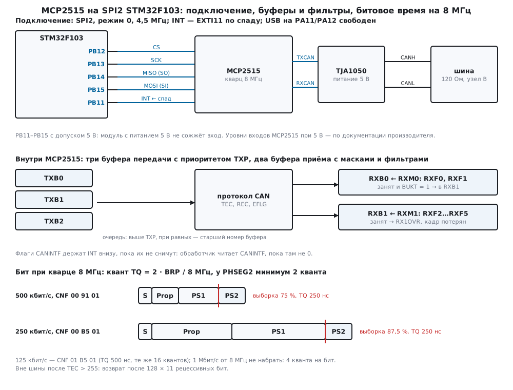
19н.1 Why an external controller and what is on the module
When there is no bxCAN or it is busy. On the STM32F103 the USB and CAN blocks share a dedicated 512-byte memory for buffers and cannot work at the same time (RM0008, p. 622 and p. 655) — this is 19.8. On top of that, on the BluePill their pins coincide: CANRX and CANTX sit on PA11 and PA12, where USBDM and USBDP are too (DocID13587, p. 31). If a device must send data to a computer over USB and listen to CAN at the same time, CAN is moved outside. The second reason is that the microcontroller has no CAN at all. The third is that a second channel is needed, and the built-in one is single. The MCP2515 covers all three cases: it is a separate CAN 2.0B controller — with its own buffers, filters, error counters and bit timing — which needs only SPI and an interrupt pin from the microcontroller.
What is on the module. A typical dirt-cheap module has the MCP2515, a crystal, a TJA1050 transceiver, CANH and CANL terminals and a jumper for the 120 Ohm terminator. The crystal on many such modules is 8 MHz; it is marked on its case, and that is the first thing to read: the bit timing is computed from it (19н.3), and half of the "the module does not see the bus" stories are code written for 16 MHz.
Power and levels are the module's main pitfall. The TJA1050 is a 5 V transceiver (the table in 19.2), and a module usually has one 5 V supply pin for both chips. Then the MCP2515 also runs from 5 V, and its SO and INT outputs drive 5 V. If they are connected to F103 pins that are not 5 V tolerant — to PA6 (MISO of SPI1) or to PB0, as with the RC522 in 18г, — the input can be damaged. So SPI2 is used here: PB12–PB15, and INT goes to PB11 — all of these pins are 5 V tolerant (DocID13587, p. 30). The other side: at a 5 V supply the MCP2515 inputs expect their own thresholds, while the F103 drives 3.3 V. Whether this is guaranteed to be enough is in the manufacturer's documentation, which is not here; not verified. The reliable option is to split the supply: the MCP2515 from 3.3 V (it can do that — per the manufacturer's documentation, not verified), the TJA1050 from 5 V.
The circuit. SPI2 sits on APB1, which is at most 36 MHz (RM0008, p. 48);
divider 8 (BR = 010, p. 743) gives 4.5 MHz: a byte takes 1.778 µs. Mode 0,
CS is a plain output PB12, as in section 18.4. INT is an active-low
output: it stays low while CANINTF has an enabled flag. On the F103 it
is caught by EXTI11 on the falling edge: AFIO_EXTICR3, field EXTI11[3:0] = 0001 — port B
(p. 191), EXTI_FTSR (p. 211), vector EXTI15_10 (position 40, p. 204);
how the signal gets to the handler is section 7.5.
void mcp_spi(const uint8_t *tx, uint8_t *rx, uint32_t n)
{
    uint32_t pm = __get_PRIMASK();
    __disable_irq();                            /* обработчик INT не влезет посреди транзакции */
    GPIOB->BRR = 1u << 12;                      /* CS вниз */
    for (uint32_t i = 0; i < n; i++) {
        while (!(SPI2->SR & SPI_SR_TXE)) {
        }
        SPI2->DR = tx[i];
        while (!(SPI2->SR & SPI_SR_RXNE)) {
        }
        rx[i] = (uint8_t)SPI2->DR;
    }
    while (SPI2->SR & SPI_SR_BSY) {
    }
    GPIOB->BSRR = 1u << 12;                     /* CS вверх: команда выполнена */
    __set_PRIMASK(pm);
}
Masking interrupts for the duration of a transaction is not decoration: the INT handler uses SPI itself, and if it breaks in between the bytes of a transaction from the main loop, the chip receives a mix of two commands.
19н.2 SPI commands and registers
The MCP2515 has no address byte like the MFRC522 in 18г: the first byte of a transaction is the command code. Nine commands:
| Command | Code | Transaction bytes | What it does |
|---|---|---|---|
| RESET | C0 |
1 | reset, configuration mode |
| READ | 03 |
2 + n | address and n registers in a row |
| WRITE | 02 |
2 + n | address and n values in a row |
| BIT MODIFY | 05 |
4 | address, mask, value: changes only the mask bits |
| READ STATUS | A0 |
2 | receive and transmit flags in one byte |
| RX STATUS | B0 |
2 | where the frames are, their type, which filter matched |
| LOAD TX BUFFER | 40, 42, 44 |
1 + 5 + n | header and data into TXB0, TXB1, TXB2 without an address |
| RTS | 81, 82, 84 |
1 | request transmission of the buffers |
| READ RX BUFFER | 90, 94 |
1 + 13 | the whole RXB0 or RXB1; the receive flag clears itself |
The codes, except RX STATUS, match the Zephyr driver. The registers the driver needs:
| Register | Address | Purpose |
|---|---|---|
| CANSTAT / CANCTRL | 0E / 0F |
current and requested mode (bits 7:5), OSM — bit 3 |
| TEC / REC | 1C / 1D |
transmit and receive error counters |
| CNF3, CNF2, CNF1 | 28, 29, 2A |
bit timing |
| CANINTE / CANINTF | 2B / 2C |
interrupt enables and flags |
| EFLG | 2D |
warning, passive, bus-off, overflows |
| TXB0CTRL…TXB2CTRL | 30, 40, 50 |
TXREQ request, TXP priority, MLOA, TXERR |
| RXB0CTRL / RXB1CTRL | 60 / 70 |
RXM filter mode, BUKT rollover, FILHIT |
| RXF0–RXF2, RXF3–RXF5 | 00…0B, 10…1B |
filters of 4 bytes each |
| RXM0 / RXM1 | 20 / 24 |
masks of 4 bytes each |
Modes. After RESET the chip is in configuration mode: CANSTAT =
0x80, CANCTRL = 0x87. Only in it can CNF1–CNF3, filters and masks be written;
in other modes the write is silently lost. In the model, writing filter RXF0
in normal mode gave 4 dropped writes, and RXF0 stayed 00 00 00 00.
A mode is requested with bits 7:5 of CANCTRL (0 — normal, 2 — loopback, 4 —
configuration) and read back in CANSTAT: the change is not instant, and the driver waits
until CANSTAT shows what was requested — like Zephyr.
Setup. mcp_init sends RESET, waits 128 µs (Zephyr waits just as
long: 128 oscillator cycles at the slowest frequency of 1 MHz), checks
CANSTAT — 0x00 or 0xFF means "no SPI link" — and with a single WRITE
command from address 0x28 writes CNF3, CNF2, CNF1 and CANINTE: the addresses are
consecutive. Then RXB0CTRL and RXB1CTRL and a check read of CNF. In the model —
7 transactions, 26 bytes and 174.2 µs, of which 128 is the wait after reset.
Switching to normal mode takes 2 transactions and 7 bytes: a BIT MODIFY and one read
of CANSTAT.
BIT MODIFY changes only the mask bits — without reading the register and without racing the chip, which sets flags in the same register itself. The driver uses it to clear CANINTF and EFLG flags, set the mode and TXP.
19н.3 Bit timing at 8 MHz
The formulas are the same as in 19.4, but with their own names and one peculiarity.
The quantum TQ = 2 · BRP / Fosc: before the BRP divider there is always a division by 2
(in Zephyr the CAN core clock is Fosc / 2, in can-calc-bit-timing for
mcp251x it is "half of the oscillator frequency"). A bit is 1 + PRSEG + PHSEG1 + PHSEG2
quanta; sampling happens after PHSEG1. The limits come from can-calc-bit-timing:
PRSEG + PHSEG1 — from 3 to 16, PHSEG2 — from 2 to 8, SJW — up to 4, BRP — from 1
to 64. So a bit has from 6 to 25 quanta. The CNF fields are written "minus one",
as with bxCAN: CNF1 = SJW and BRP, CNF2 = the BTLMODE bit, PHSEG1 and PRSEG, CNF3 =
PHSEG2 — the layout as in Zephyr.
int mcp_calc_timing(uint32_t fosc, uint32_t bitrate, mcp_timing_t *t)
{
    uint32_t fcan = fosc / 2u;          /* делитель на 2 стоит перед BRP всегда */
    for (uint32_t brp = 1; brp <= 64u; brp++) {
        if (fcan % (brp * bitrate))
            continue;                   /* только точная скорость */
        uint32_t ntq = fcan / (brp * bitrate);
        if (ntq > 25u)
            continue;                   /* больше 1 + 16 + 8 квантов не набрать */
        if (ntq < 6u)
            return -1;                  /* меньше 1 + 3 + 2: скорость недостижима */
        uint32_t ps2 = (ntq * 125u + 999u) / 1000u;    /* точка выборки не позже 87,5 % */
        if (ps2 < 2u)
            ps2 = 2u;                   /* PHSEG2 не короче 2 квантов */
        uint32_t tseg1 = ntq - 1u - ps2;
        if (tseg1 > 16u) {
            tseg1 = 16u;
            ps2 = ntq - 17u;
        }
        t->brp = (uint8_t)brp;
        t->prop = (uint8_t)(tseg1 / 2u);
        t->ps1 = (uint8_t)(tseg1 - t->prop);
        t->ps2 = (uint8_t)ps2;
        t->sjw = 1;
        t->ntq = (uint8_t)ntq;
        t->sp_permille = (uint16_t)((1000u * (ntq - ps2) + ntq / 2u) / ntq);
        t->cnf1 = (uint8_t)(((t->sjw - 1u) << 6) | (brp - 1u));
        t->cnf2 = (uint8_t)(0x80u | ((t->ps1 - 1u) << 3) | (t->prop - 1u));   /* BTLMODE: PHSEG2 из CNF3 */
        t->cnf3 = (uint8_t)(t->ps2 - 1u);
        return 0;
    }
    return -1;
}
The function takes the smallest divider — that is, the most quanta per bit — and aims at sampling no later than 87.5 %, as 19.4 recommends. The run for an 8 MHz crystal:
| Bit rate | BRP | Quantum | Quanta | 1 + Prop + PS1 + PS2 | Sampling | CNF1 CNF2 CNF3 |
|---|---|---|---|---|---|---|
| 1 Mbit/s | — | — | 4 | not reachable | — | — |
| 500 kbit/s | 1 | 250 ns | 8 | 1 + 2 + 3 + 2 | 75 % | 00 91 01 |
| 250 kbit/s | 1 | 250 ns | 16 | 1 + 6 + 7 + 2 | 87.5 % | 00 B5 01 |
| 125 kbit/s | 2 | 500 ns | 16 | 1 + 6 + 7 + 2 | 87.5 % | 01 B5 01 |
can-calc-bit-timing with a 4 MHz reference clock gave the same segments and the same
CNF for all three bit rates, and for 1 Mbit/s — "bitrate not possible".
Why 500 kbit/s gets only 75 %. From 8 MHz the quantum cannot be shorter than 2 / 8 MHz = 250 ns, and a 500 kbit/s bit is 2 µs, exactly 8 quanta. For 87.5 % PHSEG2 would have to be 1 quantum, and on the MCP2515 it is no shorter than 2. What remains is sampling at 6 / 8 = 75 %. With a 16 MHz crystal there would be 16 quanta and 87.5 %. 75 % works, but the other nodes on the bus usually sample around 87.5 %, and on a long line this node has less margin for delay.
Frequency tolerance — the formulas from 19.4: the smaller of min(PS1, PS2) / (2 · (13 · N − PS2)) and SJW / (20 · N). For 500 kbit/s (N = 8, PS1 = 3, PS2 = 2, SJW = 1): 0.98 % and 0.625 % — the node needs 0.625 %. For 250 and 125 kbit/s (N = 16, PS1 = 7, PS2 = 2): 0.485 % and 0.312 % — a tolerance of 0.312 %. The module's crystal holds its frequency much more precisely, so there is margin; but an RC oscillator instead of a crystal will not do, just as with bxCAN.
A 16 MHz crystal in the code, 8 MHz on the board. The same function for "16 MHz and
500 kbit/s" gives 16 quanta and CNF 00 B5 01 — exactly the same bytes as for
8 MHz and 250 kbit/s. Written into a module with an 8 MHz crystal, they give
250000 bit/s: the node runs at half the bus speed (the experiment is in 19н.6).
19н.4 Transmit and receive: three buffers, two buffers, INT
Transmit. A free buffer is seen with READ STATUS: bits 2, 4 and 6 are TXREQ of buffers 0, 1 and 2. Then LOAD TX BUFFER puts the header (SIDH, SIDL, EID8, EID0, DLC) and the data without an address, and RTS requests transmission.
int mcp_send(const mcp_frame_t *f, uint8_t txp)
{
    uint8_t st = mcp_read_status();     /* TXREQ буферов 0, 1, 2 — биты 2, 4, 6 */
    for (uint8_t b = 0; b < 3u; b++) {
        if (!(st & (0x04u << (2u * b)))) {
            if (mcp_load(b, f, txp))
                return -1;
            mcp_rts((uint8_t)(1u << b));
            return b;
        }
    }
    return -1;                          /* все три буфера ждут шину */
}
A frame with 8 bytes takes 4 transactions and 21 bytes over SPI, 37.3 µs: READ STATUS
(2), BIT MODIFY for TXP (4), LOAD TX BUFFER (14), RTS (1). In the model the frame
100 with data 11 22 … 88 took 114 bits on the bus with 3 stuffed
bits and CRC 72D1 — 228 µs at 500 kbit/s.
The order of the three buffers. If the bus is busy, the buffers wait, and the first to go is
the buffer with the larger TXP (3 is the highest), and on equal TXP — the one with the larger number. The chip
does not think about identifiers here. The experiment: while node B transmits
its frame, the driver queues 100, 200, 300 — they go into
TXB0, TXB1, TXB2. With equal TXP the bus got 300, 200, 100 —
the reverse of the CAN priority. With TXP 3, 2, 1 by identifier —
100, 200, 300. That is why the Zephyr driver uses a single transmit
buffer: its header says so — to avoid priority
inversion. Arbitration on the bus works as in 19.3: frame 100 from
TXB0 and frame 0F0 of node B both wait until node B finishes its previous frame, —
0F0 won, MLOA (0x20) rose in TXB0CTRL, and 100 went right after.
Receive. A received frame goes into RXB0 or RXB1, RX0IF or RX1IF rises, and INT goes low. READ RX BUFFER reads the 13 bytes of the buffer in one transaction and clears the flag by itself on the CS rise — a separate BIT MODIFY is not needed (the same in Zephyr). A plain READ of the same buffer with a separate flag clear takes 2 + 13 and another 4 bytes, 19 instead of 14.
The handler loops while CANINTF is not empty. INT is a level, while EXTI catches an edge. While at least one enabled flag is set, INT stays low, and a new frame gives no new falling edge. If the handler has not cleared everything, the next interrupt will never come.
int mcp_isr(mcp_t *m)
{
    for (m->isr_loops = 0; m->isr_loops < 8u; m->isr_loops++) {
        uint8_t f = mcp_read1(MCP_CANINTF) & m->inte;
        if (!f)
            break;                      /* флагов нет — INT поднялся, следующий спад даст EXTI */
        if (f & MCP_RX0IF)
            rx_buffer(m, 0);
        if (f & MCP_RX1IF)
            rx_buffer(m, 1);
        m->tx_done += ((f >> 2) & 1u) + ((f >> 3) & 1u) + ((f >> 4) & 1u);
        if (f & MCP_ERRIF) {
            uint8_t c[2];
            m->err_irqs++;
            m->eflg = mcp_read1(MCP_EFLG);
            mcp_read(MCP_TEC, c, 2);    /* TEC и REC подряд */
            m->tec = c[0];
            m->rec = c[1];
            if (m->eflg & (MCP_RX0OVR | MCP_RX1OVR)) {
                m->ovr++;
                mcp_bitmod(MCP_EFLG, m->eflg & (MCP_RX0OVR | MCP_RX1OVR), 0);
            }
        }
        uint8_t clr = (uint8_t)(f & ~(MCP_RX0IF | MCP_RX1IF));
        if (clr)
            mcp_bitmod(MCP_CANINTF, clr, 0);
    }
    return (int)m->isr_loops;
}
In the firmware the EXTI handler first clears its EXTI_PR bit (by writing a
one, p. 212), and only then calls mcp_isr: if a new falling edge arrives while the
handler is running, the bit is set again and the interrupt repeats.
void EXTI15_10_IRQHandler(void)
{
    if (EXTI->PR & (1u << 11)) {
        EXTI->PR = 1u << 11;                    /* снять до обработки: новый спад во время неё не пропадёт */
        mcp_isr(&M);                            /* читает CANINTF, пока там есть флаги */
    }
}
One received frame costs the handler 20 bytes over SPI — a CANINTF read (3), READ RX BUFFER (14), a second CANINTF read (3) — and 35.6 µs. A stream of 20 frames of 8 bytes back to back at 500 kbit/s: between the starts of frames — no less than 226 µs, all 20 received, SPI busy 15.0 % of the time. This estimate ignores the gaps between bytes and the CPU time — they were not measured on hardware.
Two receive buffers and rollover. Without filters (RXM = 11) every frame first asks for RXB0. If it is busy and the BUKT bit in RXB0CTRL is clear, the frame is lost — with the RX0OVR flag, even if RXB1 is empty. With BUKT = 1 it goes to RXB1. The experiment: interrupts are masked for 1000 µs (say, by another handler), and during that time node B sends three frames back to back. BUKT = 0: 1 received, 2 lost. BUKT = 1: 2 received, 1 lost. Two buffers are a margin for one handler delay, no more: at 500 kbit/s a frame with 8 bytes lasts 226–254 µs.
The "one message per interrupt" handler. A common pattern: read
RXB0, and if it is empty — RXB1, and return. With rollover both buffers are full,
the handler takes one — INT stays low. The experiment: two frames back to back with
interrupts masked, then four more 1 ms apart. Such a handler received
1 frame out of 6, 3 were lost, and INT keeps hanging low with CANINTF = 0x23:
unread RX0IF and RX1IF and ERRIF from the overflows. One call of the full
mcp_isr took the two stuck frames and raised INT. The same experiment with
mcp_isr from the start — all 6 received.
19н.5 Masks and filters
A filter compares the identifier not as a whole, but only in the bits where the mask has a one. RXB0 has one mask RXM0 and filters RXF0, RXF1; RXB1 has mask RXM1 and RXF2–RXF5. A frame that passed an RXB0 filter goes to RXB0 (or to RXB1 on rollover); otherwise the RXB1 filters are checked. Masks and filters are 4 registers each; for an extended identifier all 29 bits are spread over SIDH, SIDL, EID8 and EID0, and the filter's SIDL also has the EXIDE bit: the filter catches either standard frames or extended ones.
static void id_bytes(uint32_t id, uint8_t ext, uint8_t b[4])
{
    if (ext) {
        b[0] = (uint8_t)(id >> 21);
        b[1] = (uint8_t)((((id >> 18) & 7u) << 5) | 0x08u | ((id >> 16) & 3u));   /* 0x08 — EXIDE */
        b[2] = (uint8_t)(id >> 8);
        b[3] = (uint8_t)id;
    } else {
        b[0] = (uint8_t)(id >> 3);
        b[1] = (uint8_t)((id & 7u) << 5);
        b[2] = 0;                       /* у стандартного кадра здесь — байты данных 0 и 1 */
        b[3] = 0;
    }
}
The header layout matches what Zephyr writes into a transmit buffer.
The experiment setup: RXM0 = 7FF, RXF0 = 100, RXF1 = 101 —
standard; RXM1 = 1FFFFF00 — a mask of the extended kind, RXF2 =
18DAF100 (extended), RXF3 = 7E0 (standard), RXF4 and RXF5 —
copies of RXF2, so that empty filters do not catch extra frames. Node B sends frames, and
here is where they ended up:
| Frame | Data | Where | FILHIT | RX STATUS |
|---|---|---|---|---|
100 |
01 02 |
RXB0 | RXF0 | 40 |
101 |
03 |
RXB0 | RXF1 | 41 |
102 |
04 |
not accepted | — | — |
18DAF110, extended |
02 10 |
RXB1 | RXF2 | 92 |
18DAF210, extended |
02 10 |
not accepted | — | — |
100, extended |
05 |
not accepted | — | — |
7E0 |
00 11 |
RXB1 | RXF3 | 83 |
7E0 |
02 11 |
not accepted | — | — |
The extended 100 did not hit RXF0, although the number is the same: RXF0 has EXIDE = 0.
18DAF210 did not pass: mask 1FFFFF00 compares everything except the low
byte, and where the filter has F1, the frame has F2. The most
unexpected are the two 7E0 frames. For a standard frame the EID bits of the mask and the
filter are compared with data bytes 0 and 1: mask 1FFFFF00 gives
FF in EID8 and 00 in EID0, while RXF3 has zeros there. The frame with first byte 00 passed,
the one with 02 did not. Handy if you need a filter on the first data byte, and
puzzling if a mask meant for extended frames touched standard ones (this
behavior is per the manufacturer's documentation, not verified; the model implements it this way). RX STATUS in the model works like this:
bits 7:6 — which buffer holds the frame, bit 4 — extended, bits 2:0 — the filter number; 92 — RXB1,
extended, RXF2.
Filters can be written only in configuration mode (19н.2): the driver enters it, writes the masks and filters, sets RXM = 00 in both RXBnCTRL and returns to normal mode.
19н.6 Errors, bus-off and self-test
The counters and rules are the same as in 19.7: TEC grows by 8 per transmit error and drops by 1 per success; at 128 the node is passive; at TEC above 255 — disconnected; REC grows on receive errors. Here they are visible in TEC, REC and EFLG, and a change of state raises ERRIF — the handler reads EFLG and both counters.
A lone node. Node B is disconnected, the driver sends one frame. Nobody is there to
acknowledge it: an ACK error, TEC + 8, a retry. After 16 attempts TEC = 128, the node
is passive — 4037.3 µs after the frame was queued. From then on an ACK error of
a passive node does not increase the counter: in 10 ms there were 39 attempts, TEC stays
at 128, EFLG = 0x15 (TXEP, TXWAR, EWARN), TXB0CTRL has TXREQ and TXERR
(0x18). Node B came back — the frame went out, TEC = 127, EFLG = 0x05:
passive state lifted, the warning remained.
A single attempt. The OSM bit in CANCTRL: the frame is sent once. The same
lone node: 1 attempt, TEC = 8, TXERR set, TXREQ cleared (TXB0CTRL =
0x10). This is done when repeating a stale frame makes no sense.
Bus-off. CANH and CANL are shorted: the dominant level does not reach the bus,
the controller sees something other than what it sent — a bit error, + 8 on
every attempt, for a passive node too. Passive after 16 attempts,
613.3 µs; disconnected after 32 attempts, 1445.3 µs, EFLG = 0x35 (TXBO
on top). The short was removed — the node came back by itself after 2816 µs: 128 × 11 =
1408 recessive bits of 2 µs each (coming back without the program's help is per the
manufacturer's documentation, not verified), TEC = 0, and the frame waiting in TXB0
went out.
The wrong crystal. The code assumed 16 MHz, the module has 8 MHz: the node runs
at 250000 bit/s, the bus at 500000. Five frames of node B are
garbage for the MCP2515, REC = 5. Its own frame — error after error: 32 attempts, and the node
is disconnected, EFLG = 0x35.
Self-test in loopback. In loopback mode (2) the frame does not go out to the
bus: the chip transmits it to itself, does not wait for an acknowledgement and puts it into a
receive buffer through the same filters. No transceiver and no second board are needed.
mcp_selftest switches the mode, sends frame 5A5 with 8 bytes, waits for it in the
receive queue, compares it and restores normal mode: 28 transactions, 107
bytes, 350.2 µs; the frame is 118 bits with 7 stuff bits, node B saw nothing.
The firmware does this at startup: it checks SPI, the modes, the buffers and the filters
before going onto the bus. What loopback does not check is the transceiver,
the wires, the terminators and the bit rate: in the wrong-crystal experiment the self-test
passed too, in 580.2 µs, — inside the chip the bit rate always matches
itself.
A frame bit by bit. The model builds frames itself: SOF, identifier, RTR
or SRR and IDE, DLC, data, CRC-15 (polynomial 0x4599), a stuff bit after
five equal ones, then the CRC delimiter, ACK, EOF and the interframe space.
The length of the run's frames and of 1000 random frames matched canframelen.c from
can-utils — in all 1000. Frame 100 with 8 zero bytes — 126 bits,
of them 15 stuff bits; frame 0AA with 8 bytes AA — 112 bits and 1 stuff bit.
19н.7 Pitfalls
The module is silent: CANSTAT reads 0x00 or 0xFF. No SPI link:
SO and SI swapped, CS does not go low, no power. The driver does not go
past RESET.
Code for 16 MHz, an 8 MHz crystal. CNF 00 B5 01 for "500 kbit/s" on
an 8 MHz crystal is 250000 bit/s. The node accumulates errors and leaves the bus, while
the loopback self-test passes. Read the marking on the crystal.
5 V on a pin that is not tolerant. On a module with a single 5 V supply the SO and INT outputs are 5 V too. PA6 and PB0 of the F103 are not 5 V tolerant (p. 29); PB11–PB15 are tolerant (p. 30).
1 Mbit/s cannot be configured. From 8 MHz there are 4 quanta per bit, and at least 6 are needed. 500 kbit/s comes with sampling at 75 %, not 87.5 %.
The interrupt came once and never again. The handler did not clear all flags: INT stayed low, there is no more falling edge. Loop while CANINTF is not empty (19н.4).
Frames are lost with two empty buffers. BUKT is clear: with RXB0 busy the frame disappears with RX0OVR, RXB1 sits empty. Turn rollover on.
Frames go out in the wrong order. Three buffers with equal TXP go from the higher number, not from the lower identifier. TXP by identifier or a single transmit buffer.
A standard-frame filter does not pass everything. The mask's EID bits of a standard frame compare data bytes 0 and 1. For standard frames — a mask with zeros in EID8 and EID0.
Filters "do not get written". CNF, masks and filters can be written only in configuration mode; in normal mode the write is lost without an error.
The handler breaks into a transaction. The main loop and the interrupt share one SPI: main-loop transactions run with interrupts masked.
19н.8 Summary
- The MCP2515 is a separate CAN 2.0B controller on SPI: it helps when the F103 has USB busy (shared 512-byte memory and shared pins PA11, PA12), when there is no CAN or a second channel is needed.
- Connection: SPI2 on PB12–PB15, 36 MHz / 8 = 4.5 MHz, mode 0; INT — PB11, EXTI11 on the falling edge; 5 V tolerant pins.
- Nine commands: RESET
C0, READ03, WRITE02, BIT MODIFY05, READ STATUSA0, RX STATUSB0, LOAD TX BUFFER40, RTS80, READ RX BUFFER90. - An 8 MHz crystal: a quantum from 250 ns; 500 kbit/s —
00 91 01, sampling 75 %; 250 kbit/s —00 B5 01and 125 kbit/s —01 B5 01, sampling 87.5 %; 1 Mbit/s — impossible. - A frame to send — 21 bytes over SPI, 37.3 µs; receiving a frame in the handler — 20 bytes, 35.6 µs.
- The three transmit buffers go by TXP and number, not by identifier.
- The INT handler is a loop until CANINTF is empty; BUKT = 1 saves one frame.
- The mask of a standard frame compares data bytes 0 and 1 in the EID bits.
- A lone node: 16 attempts to TEC = 128 and then endlessly; a shorted line: 32 attempts to bus-off, coming back after 1408 bits.
- Loopback checks the chip and the driver, but not the transceiver and not the bit rate.
Full sources
mcp19n.h — MCP2515 commands, registers and bits, the driver interface.
/* mcp19n.h — раздел 19н: драйвер CAN-контроллера MCP2515 по SPI без регистров STM32.
 * Драйвер говорит с микросхемой через две функции платформы: mcp_spi и mcp_delay_us.
 * В прошивке fw19n.c их даёт SPI2 STM32F103, в стенде host19n.c — модель model19n.py.
 * Коды команд SPI, адреса CANSTAT…RXB1CTRL, биты CANINTF и EFLG, поля CNF1–CNF3 совпадают с драйвером
 * Zephyr (drivers/can/can_mcp2515.h); команда RX STATUS, адреса фильтров и масок, биты TXBnCTRL,
 * RXBnCTRL и CANCTRL сверх режима — по документации производителя (в проекте её нет, не проверено). */
#ifndef MCP19N_H
#define MCP19N_H
#include <stdint.h>

/* ── команды SPI ──────────────────────────────────────────────────────── */
#define MCP_RESET       0xC0u
#define MCP_READ        0x03u
#define MCP_WRITE       0x02u
#define MCP_BITMOD      0x05u           /* адрес, маска, значение */
#define MCP_READ_STATUS 0xA0u
#define MCP_RX_STATUS   0xB0u
#define MCP_LOAD_TX     0x40u           /* | 0, 2, 4 — с TXBnSIDH буфера 0, 1, 2 */
#define MCP_RTS         0x80u           /* | биты 0–2 — буферы TXB0–TXB2 */
#define MCP_READ_RX     0x90u           /* | 0 — RXB0SIDH, | 4 — RXB1SIDH; флаг RXnIF снимается сам */

/* ── регистры ─────────────────────────────────────────────────────────── */
#define MCP_RXF0     0x00u              /* фильтры RXF0–RXF2: 0x00, 0x04, 0x08 */
#define MCP_RXF3     0x10u              /* фильтры RXF3–RXF5: 0x10, 0x14, 0x18 */
#define MCP_CANSTAT  0x0Eu
#define MCP_CANCTRL  0x0Fu
#define MCP_TEC      0x1Cu
#define MCP_REC      0x1Du
#define MCP_RXM0     0x20u              /* маски RXM0 и RXM1: 0x20, 0x24 */
#define MCP_CNF3     0x28u
#define MCP_CNF2     0x29u
#define MCP_CNF1     0x2Au
#define MCP_CANINTE  0x2Bu
#define MCP_CANINTF  0x2Cu
#define MCP_EFLG     0x2Du
#define MCP_TXB0CTRL 0x30u              /* TXB1CTRL 0x40, TXB2CTRL 0x50 */
#define MCP_RXB0CTRL 0x60u
#define MCP_RXB1CTRL 0x70u

/* режимы: CANCTRL.REQOP и CANSTAT.OPMOD, биты 7:5 */
#define MCP_MODE_NORMAL   0u
#define MCP_MODE_LOOPBACK 2u
#define MCP_MODE_LISTEN   3u
#define MCP_MODE_CONFIG   4u
#define MCP_CANCTRL_OSM   0x08u         /* одна попытка передачи */

/* CANINTE / CANINTF */
#define MCP_RX0IF 0x01u
#define MCP_RX1IF 0x02u
#define MCP_TX0IF 0x04u
#define MCP_TX1IF 0x08u
#define MCP_TX2IF 0x10u
#define MCP_ERRIF 0x20u
#define MCP_MERRF 0x80u

/* EFLG */
#define MCP_EWARN  0x01u
#define MCP_TXEP   0x10u
#define MCP_TXBO   0x20u
#define MCP_RX0OVR 0x40u
#define MCP_RX1OVR 0x80u

/* TXBnCTRL и RXBnCTRL */
#define MCP_TXREQ  0x08u
#define MCP_TXERR  0x10u
#define MCP_MLOA   0x20u
#define MCP_RXM_ANY 0x60u               /* RXM = 11: фильтры выключены, принимать всё */
#define MCP_BUKT   0x04u                /* RXB0 полон — кадр уходит в RXB1 */

typedef struct {
    uint32_t id;
    uint8_t ext, rtr, dlc, buf;         /* buf — в каком буфере приёма лежал кадр */
    uint8_t data[8];
} mcp_frame_t;

typedef struct {
    uint8_t brp, prop, ps1, ps2, sjw;   /* в квантах; brp — делитель 1…64 */
    uint8_t ntq;                        /* квантов на бит: 1 + prop + ps1 + ps2 */
    uint16_t sp_permille;               /* точка выборки, ‰ */
    uint8_t cnf1, cnf2, cnf3;
} mcp_timing_t;

#define MCP_RXQ 16u

typedef struct {
    mcp_timing_t tm;
    uint8_t inte;                       /* разрешённые прерывания CANINTE */
    uint8_t canstat0, canctrl0;         /* CANSTAT и CANCTRL сразу после RESET */
    uint8_t eflg, tec, rec;             /* последнее, что видел обработчик ошибок */
    uint32_t mode_polls;                /* чтений CANSTAT в последней смене режима */
    uint32_t isr_loops;                 /* проходов цикла в последнем mcp_isr */
    uint32_t rx_count, rx_qlost, tx_done, ovr, err_irqs;
    mcp_frame_t rxq[MCP_RXQ];
    uint8_t rx_head, rx_tail;
} mcp_t;

enum { MCP_OK, MCP_ENOCHIP, MCP_ETIMING, MCP_EMODE, MCP_EBUSY, MCP_EVERIFY, MCP_ESELF };

/* ── платформа: даёт прошивка или стенд ───────────────────────────────── */
void mcp_spi(const uint8_t *tx, uint8_t *rx, uint32_t n);   /* CS вниз, n байт, CS вверх */
void mcp_delay_us(uint32_t us);

/* ── драйвер ──────────────────────────────────────────────────────────── */
void mcp_read(uint8_t reg, uint8_t *d, uint32_t n);
uint8_t mcp_read1(uint8_t reg);
void mcp_write(uint8_t reg, const uint8_t *d, uint32_t n);
void mcp_bitmod(uint8_t reg, uint8_t mask, uint8_t v);
uint8_t mcp_read_status(void);
uint8_t mcp_rx_status(void);
int mcp_calc_timing(uint32_t fosc, uint32_t bitrate, mcp_timing_t *t);
int mcp_init(mcp_t *m, uint32_t fosc, uint32_t bitrate, uint8_t bukt);
int mcp_set_mode(mcp_t *m, uint8_t mode);
void mcp_set_filter(uint8_t n, uint32_t id, uint8_t ext);   /* только в режиме конфигурации */
void mcp_set_mask(uint8_t n, uint32_t mask, uint8_t ext);
void mcp_use_filters(uint8_t on, uint8_t bukt);
int mcp_load(uint8_t buf, const mcp_frame_t *f, uint8_t txp);
void mcp_rts(uint8_t bufs);
int mcp_send(const mcp_frame_t *f, uint8_t txp);            /* свободный буфер, загрузка, RTS */
int mcp_isr(mcp_t *m);                                      /* по INT: пока есть флаги */
int mcp_pop(mcp_t *m, mcp_frame_t *f);
int mcp_selftest(mcp_t *m);                                 /* кадр сам себе в режиме loopback */

#endif
mcp19n.c — the driver without STM32 registers: the part shared by the firmware and the bench.
/* mcp19n.c — раздел 19н: драйвер MCP2515 — команды SPI, битовое время, режимы, фильтры и маски,
 * три буфера передачи, приём по INT с циклом до пустого CANINTF, ошибки, самопроверка в loopback.
 * Без регистров STM32: общая часть прошивки fw19n.c и стенда host19n.c. */
#include <string.h>
#include "mcp19n.h"

/* ── команды SPI ──────────────────────────────────────────────────────── */
void mcp_read(uint8_t reg, uint8_t *d, uint32_t n)
{
    uint8_t tx[16] = {MCP_READ, reg}, rx[16];
    mcp_spi(tx, rx, n + 2u);            /* адрес растёт сам: n регистров подряд */
    memcpy(d, rx + 2, n);
}

uint8_t mcp_read1(uint8_t reg)
{
    uint8_t v;
    mcp_read(reg, &v, 1);
    return v;
}

void mcp_write(uint8_t reg, const uint8_t *d, uint32_t n)
{
    uint8_t tx[16] = {MCP_WRITE, reg}, rx[16];
    memcpy(tx + 2, d, n);
    mcp_spi(tx, rx, n + 2u);
}

void mcp_bitmod(uint8_t reg, uint8_t mask, uint8_t v)
{
    uint8_t tx[4] = {MCP_BITMOD, reg, mask, v}, rx[4];
    mcp_spi(tx, rx, 4);                 /* меняются только биты маски — без чтения регистра */
}

uint8_t mcp_read_status(void)
{
    uint8_t tx[2] = {MCP_READ_STATUS, 0}, rx[2];
    mcp_spi(tx, rx, 2);
    return rx[1];                       /* RX0IF, RX1IF, TXREQ и TXnIF трёх буферов в одном байте */
}

uint8_t mcp_rx_status(void)
{
    uint8_t tx[2] = {MCP_RX_STATUS, 0}, rx[2];
    mcp_spi(tx, rx, 2);
    return rx[1];                       /* 7:6 — где кадры, 4:3 — тип, 2:0 — какой фильтр */
}

/* ── битовое время: TQ = 2 · BRP / Fosc, бит = 1 + PRSEG + PHSEG1 + PHSEG2 квантов ── */
int mcp_calc_timing(uint32_t fosc, uint32_t bitrate, mcp_timing_t *t)
{
    uint32_t fcan = fosc / 2u;          /* делитель на 2 стоит перед BRP всегда */
    for (uint32_t brp = 1; brp <= 64u; brp++) {
        if (fcan % (brp * bitrate))
            continue;                   /* только точная скорость */
        uint32_t ntq = fcan / (brp * bitrate);
        if (ntq > 25u)
            continue;                   /* больше 1 + 16 + 8 квантов не набрать */
        if (ntq < 6u)
            return -1;                  /* меньше 1 + 3 + 2: скорость недостижима */
        uint32_t ps2 = (ntq * 125u + 999u) / 1000u;    /* точка выборки не позже 87,5 % */
        if (ps2 < 2u)
            ps2 = 2u;                   /* PHSEG2 не короче 2 квантов */
        uint32_t tseg1 = ntq - 1u - ps2;
        if (tseg1 > 16u) {
            tseg1 = 16u;
            ps2 = ntq - 17u;
        }
        t->brp = (uint8_t)brp;
        t->prop = (uint8_t)(tseg1 / 2u);
        t->ps1 = (uint8_t)(tseg1 - t->prop);
        t->ps2 = (uint8_t)ps2;
        t->sjw = 1;
        t->ntq = (uint8_t)ntq;
        t->sp_permille = (uint16_t)((1000u * (ntq - ps2) + ntq / 2u) / ntq);
        t->cnf1 = (uint8_t)(((t->sjw - 1u) << 6) | (brp - 1u));
        t->cnf2 = (uint8_t)(0x80u | ((t->ps1 - 1u) << 3) | (t->prop - 1u));   /* BTLMODE: PHSEG2 из CNF3 */
        t->cnf3 = (uint8_t)(t->ps2 - 1u);
        return 0;
    }
    return -1;
}

/* ── сброс, настройка, режимы ─────────────────────────────────────────── */
int mcp_set_mode(mcp_t *m, uint8_t mode)
{
    mcp_bitmod(MCP_CANCTRL, 0xE0u, (uint8_t)(mode << 5));
    for (m->mode_polls = 1; m->mode_polls <= 100u; m->mode_polls++) {
        if ((mcp_read1(MCP_CANSTAT) >> 5) == mode)
            return MCP_OK;              /* режим меняется не сразу: ждём OPMOD */
        mcp_delay_us(10);
    }
    return MCP_EMODE;
}

void mcp_use_filters(uint8_t on, uint8_t bukt)
{
    mcp_bitmod(MCP_RXB0CTRL, MCP_RXM_ANY | MCP_BUKT, (uint8_t)((on ? 0u : MCP_RXM_ANY) | (bukt ? MCP_BUKT : 0u)));
    mcp_bitmod(MCP_RXB1CTRL, MCP_RXM_ANY, on ? 0u : MCP_RXM_ANY);
}

int mcp_init(mcp_t *m, uint32_t fosc, uint32_t bitrate, uint8_t bukt)
{
    uint8_t cmd = MCP_RESET, rx, cnf[4], back[3];
    memset(m, 0, sizeof *m);
    mcp_spi(&cmd, &rx, 1);
    mcp_delay_us(128);                  /* запуск генератора: 128 тактов при 1 МГц, как в Zephyr */
    m->canstat0 = mcp_read1(MCP_CANSTAT);
    m->canctrl0 = mcp_read1(MCP_CANCTRL);
    if ((m->canstat0 >> 5) != MCP_MODE_CONFIG)
        return MCP_ENOCHIP;             /* 0x00 или 0xFF — нет связи по SPI */
    if (mcp_calc_timing(fosc, bitrate, &m->tm))
        return MCP_ETIMING;
    m->inte = MCP_RX0IF | MCP_RX1IF | MCP_TX0IF | MCP_TX1IF | MCP_TX2IF | MCP_ERRIF;
    cnf[0] = m->tm.cnf3;                /* CNF3, CNF2, CNF1, CANINTE — подряд одной записью */
    cnf[1] = m->tm.cnf2;
    cnf[2] = m->tm.cnf1;
    cnf[3] = m->inte;
    mcp_write(MCP_CNF3, cnf, 4);
    mcp_use_filters(0, bukt);
    mcp_read(MCP_CNF3, back, 3);
    if (memcmp(back, cnf, 3))
        return MCP_EVERIFY;             /* CNF пишутся только в режиме конфигурации */
    return MCP_OK;
}

/* ── фильтры и маски: SIDH, SIDL, EID8, EID0 ──────────────────────────── */
static void id_bytes(uint32_t id, uint8_t ext, uint8_t b[4])
{
    if (ext) {
        b[0] = (uint8_t)(id >> 21);
        b[1] = (uint8_t)((((id >> 18) & 7u) << 5) | 0x08u | ((id >> 16) & 3u));   /* 0x08 — EXIDE */
        b[2] = (uint8_t)(id >> 8);
        b[3] = (uint8_t)id;
    } else {
        b[0] = (uint8_t)(id >> 3);
        b[1] = (uint8_t)((id & 7u) << 5);
        b[2] = 0;                       /* у стандартного кадра здесь — байты данных 0 и 1 */
        b[3] = 0;
    }
}

void mcp_set_filter(uint8_t n, uint32_t id, uint8_t ext)
{
    uint8_t b[4];
    id_bytes(id, ext, b);
    mcp_write((uint8_t)(n < 3u ? 4u * n : MCP_RXF3 + 4u * (n - 3u)), b, 4);
}

void mcp_set_mask(uint8_t n, uint32_t mask, uint8_t ext)
{
    uint8_t b[4];
    id_bytes(mask, ext, b);
    b[1] &= (uint8_t)~0x08u;            /* у маски бита EXIDE нет */
    mcp_write((uint8_t)(MCP_RXM0 + 4u * n), b, 4);
}

/* ── передача ─────────────────────────────────────────────────────────── */
int mcp_load(uint8_t buf, const mcp_frame_t *f, uint8_t txp)
{
    uint8_t tx[14], rx[14];
    if (buf > 2u || f->dlc > 8u)
        return -1;
    mcp_bitmod((uint8_t)(MCP_TXB0CTRL + 0x10u * buf), 0x03u, txp);   /* TXP: 3 — старший */
    tx[0] = (uint8_t)(MCP_LOAD_TX | (2u * buf));
    id_bytes(f->id, f->ext, tx + 1);
    tx[5] = (uint8_t)(f->dlc | (f->rtr ? 0x40u : 0u));
    memcpy(tx + 6, f->data, f->dlc);
    mcp_spi(tx, rx, 6u + f->dlc);       /* без адреса: команда сама указывает на TXBnSIDH */
    return 0;
}

void mcp_rts(uint8_t bufs)
{
    uint8_t tx = (uint8_t)(MCP_RTS | (bufs & 7u)), rx;
    mcp_spi(&tx, &rx, 1);
}

int mcp_send(const mcp_frame_t *f, uint8_t txp)
{
    uint8_t st = mcp_read_status();     /* TXREQ буферов 0, 1, 2 — биты 2, 4, 6 */
    for (uint8_t b = 0; b < 3u; b++) {
        if (!(st & (0x04u << (2u * b)))) {
            if (mcp_load(b, f, txp))
                return -1;
            mcp_rts((uint8_t)(1u << b));
            return b;
        }
    }
    return -1;                          /* все три буфера ждут шину */
}

/* ── приём и прерывание ───────────────────────────────────────────────── */
static void rx_buffer(mcp_t *m, uint8_t n)
{
    uint8_t tx[14] = {(uint8_t)(MCP_READ_RX | (n << 2))}, rx[14];
    const uint8_t *h = rx + 1;
    mcp_spi(tx, rx, 14);                /* 13 байт буфера; на подъёме CS снимается RXnIF */
    mcp_frame_t f;
    memset(&f, 0, sizeof f);
    if (h[1] & 0x08u) {
        f.ext = 1;
        f.id = ((uint32_t)h[0] << 21) | ((uint32_t)(h[1] >> 5) << 18) | ((uint32_t)(h[1] & 3u) << 16)
             | ((uint32_t)h[2] << 8) | h[3];
        f.rtr = (uint8_t)((h[4] >> 6) & 1u);
    } else {
        f.id = ((uint32_t)h[0] << 3) | (h[1] >> 5);
        f.rtr = (uint8_t)((h[1] >> 4) & 1u);      /* SRR в SIDL — запрос у стандартного кадра */
    }
    f.dlc = (uint8_t)(h[4] & 0x0Fu);
    if (f.dlc > 8u)
        f.dlc = 8;
    f.buf = n;
    memcpy(f.data, h + 5, 8);
    m->rx_count++;
    uint8_t next = (uint8_t)((m->rx_head + 1u) % MCP_RXQ);
    if (next == m->rx_tail) {
        m->rx_qlost++;                  /* программная очередь полна */
        return;
    }
    m->rxq[m->rx_head] = f;
    m->rx_head = next;
}

int mcp_isr(mcp_t *m)
{
    for (m->isr_loops = 0; m->isr_loops < 8u; m->isr_loops++) {
        uint8_t f = mcp_read1(MCP_CANINTF) & m->inte;
        if (!f)
            break;                      /* флагов нет — INT поднялся, следующий спад даст EXTI */
        if (f & MCP_RX0IF)
            rx_buffer(m, 0);
        if (f & MCP_RX1IF)
            rx_buffer(m, 1);
        m->tx_done += ((f >> 2) & 1u) + ((f >> 3) & 1u) + ((f >> 4) & 1u);
        if (f & MCP_ERRIF) {
            uint8_t c[2];
            m->err_irqs++;
            m->eflg = mcp_read1(MCP_EFLG);
            mcp_read(MCP_TEC, c, 2);    /* TEC и REC подряд */
            m->tec = c[0];
            m->rec = c[1];
            if (m->eflg & (MCP_RX0OVR | MCP_RX1OVR)) {
                m->ovr++;
                mcp_bitmod(MCP_EFLG, m->eflg & (MCP_RX0OVR | MCP_RX1OVR), 0);
            }
        }
        uint8_t clr = (uint8_t)(f & ~(MCP_RX0IF | MCP_RX1IF));
        if (clr)
            mcp_bitmod(MCP_CANINTF, clr, 0);
    }
    return (int)m->isr_loops;
}

int mcp_pop(mcp_t *m, mcp_frame_t *f)
{
    if (m->rx_tail == m->rx_head)
        return 0;
    *f = m->rxq[m->rx_tail];
    m->rx_tail = (uint8_t)((m->rx_tail + 1u) % MCP_RXQ);
    return 1;
}

/* ── самопроверка: кадр уходит и возвращается внутри микросхемы, шина не нужна ── */
int mcp_selftest(mcp_t *m)
{
    static const mcp_frame_t t = {0x5A5u, 0, 0, 8, 0, {0x55, 0xAA, 0x00, 0xFF, 0x01, 0x02, 0x04, 0x08}};
    mcp_frame_t r;
    int got = 0;
    if (mcp_set_mode(m, MCP_MODE_LOOPBACK) != MCP_OK)
        return MCP_EMODE;
    while (mcp_pop(m, &r)) {
    }
    if (mcp_send(&t, 0) < 0)
        return MCP_EBUSY;
    for (uint32_t i = 0; i < 1000u && !got; i++) {
        mcp_isr(m);
        got = mcp_pop(m, &r);
        if (!got)
            mcp_delay_us(10);
    }
    int ok = got && r.id == t.id && !r.ext && r.dlc == t.dlc && !memcmp(r.data, t.data, 8);
    if (mcp_set_mode(m, MCP_MODE_NORMAL) != MCP_OK)
        return MCP_EMODE;
    return ok ? MCP_OK : MCP_ESELF;
}
fw19n.c — STM32F103 firmware: SPI2, EXTI11, output to USART1.
/* fw19n.c — раздел 19н: модуль MCP2515 + TJA1050 на STM32F103 (BluePill), 72 МГц; USB (PA11, PA12) свободен.
 * SPI2: PB12 — CS (ведём сами), PB13 — SCK, PB14 — MISO, PB15 — MOSI; PB11 — INT модуля, EXTI11 по спаду.
 * Все пять выводов — с допуском 5 В (FT). SPI — режим 0, старшим битом вперёд, APB1 36 МГц / 8 = 4,5 МГц.
 * CAN 500 кбит/с от кварца модуля 8 МГц, ролловер RXB0 → RXB1. Кадры и ошибки — в USART1 (PA9, 115200).
 * Тактирование до 72 МГц — как в разделе 6 (здесь не повторяется); APB1 = 36 МГц. */
#include "stm32f10x.h"
#include "mcp19n.h"

#define CPU_HZ 72000000u
#define MCP_FOSC 8000000u
#define SPI_BR SPI_CR1_BR_1                     /* BR = 010: fPCLK / 8 */

_Static_assert(SPI_BR == 0x10u, "BR[2:0] = 010 — биты 5:3 SPI_CR1");
_Static_assert(36000000u / 8u == 4500000u, "SPI2: 36 МГц / 8 = 4,5 МГц");
_Static_assert(CPU_HZ / 115200u == 625u, "USART1: BRR = 625 — 115 200 бод");

static mcp_t M;

/* ── платформа драйвера ───────────────────────────────────────────────── */
void mcp_spi(const uint8_t *tx, uint8_t *rx, uint32_t n)
{
    uint32_t pm = __get_PRIMASK();
    __disable_irq();                            /* обработчик INT не влезет посреди транзакции */
    GPIOB->BRR = 1u << 12;                      /* CS вниз */
    for (uint32_t i = 0; i < n; i++) {
        while (!(SPI2->SR & SPI_SR_TXE)) {
        }
        SPI2->DR = tx[i];
        while (!(SPI2->SR & SPI_SR_RXNE)) {
        }
        rx[i] = (uint8_t)SPI2->DR;
    }
    while (SPI2->SR & SPI_SR_BSY) {
    }
    GPIOB->BSRR = 1u << 12;                     /* CS вверх: команда выполнена */
    __set_PRIMASK(pm);
}

void mcp_delay_us(uint32_t us)
{
    uint32_t t0 = DWT->CYCCNT;
    while (DWT->CYCCNT - t0 < us * (CPU_HZ / 1000000u)) {
    }
}

void EXTI15_10_IRQHandler(void)
{
    if (EXTI->PR & (1u << 11)) {
        EXTI->PR = 1u << 11;                    /* снять до обработки: новый спад во время неё не пропадёт */
        mcp_isr(&M);                            /* читает CANINTF, пока там есть флаги */
    }
}

/* ── вывод в USART1 ───────────────────────────────────────────────────── */
static void put(char c)
{
    while (!(USART1->SR & USART_SR_TXE)) {
    }
    USART1->DR = (uint8_t)c;
}

static void puts_(const char *s)
{
    while (*s)
        put(*s++);
}

static void hex(uint32_t v, int digits)
{
    static const char h[] = "0123456789ABCDEF";
    while (digits--)
        put(h[(v >> (4 * digits)) & 15u]);
}

static void board_init(void)
{
    CoreDebug->DEMCR |= CoreDebug_DEMCR_TRCENA_Msk;
    DWT->CYCCNT = 0;
    DWT->CTRL |= DWT_CTRL_CYCCNTENA_Msk;
    RCC->APB2ENR |= RCC_APB2ENR_IOPAEN | RCC_APB2ENR_IOPBEN | RCC_APB2ENR_IOPCEN | RCC_APB2ENR_AFIOEN
                  | RCC_APB2ENR_USART1EN;
    RCC->APB1ENR |= RCC_APB1ENR_SPI2EN;
    GPIOB->BSRR = (1u << 12) | (1u << 11);      /* CS вверх; подтяжка INT вверх */
    GPIOB->CRH = (GPIOB->CRH & 0x00000FFFu)
               | 0x8u << 12                     /* PB11 — вход с подтяжкой: INT */
               | 0x3u << 16                     /* PB12 — выход 50 МГц: CS */
               | 0xBu << 20                     /* PB13 — SCK, альтернативная функция */
               | 0x4u << 24                     /* PB14 — MISO, вход без подтяжки */
               | 0xBu << 28;                    /* PB15 — MOSI, альтернативная функция */
    GPIOA->CRH = (GPIOA->CRH & ~(0xFu << 4)) | 0xBu << 4;      /* PA9 — USART1_TX */
    GPIOC->CRH = (GPIOC->CRH & ~(0xFu << 20)) | 0x2u << 20;    /* PC13 — светодиод платы */
    SPI2->CR1 = SPI_CR1_MSTR | SPI_BR | SPI_CR1_SSM | SPI_CR1_SSI;   /* ведущий, режим 0, NSS программный */
    SPI2->CR1 |= SPI_CR1_SPE;
    USART1->BRR = CPU_HZ / 115200u;
    USART1->CR1 = USART_CR1_UE | USART_CR1_TE;
}

static void exti_init(void)
{
    AFIO->EXTICR[2] = (AFIO->EXTICR[2] & ~(0xFu << 12)) | 0x1u << 12;   /* EXTI11 ← PB11 */
    EXTI->FTSR |= 1u << 11;                     /* INT активен низким: прерывание по спаду */
    EXTI->IMR |= 1u << 11;
    EXTI->PR = 1u << 11;
    NVIC_EnableIRQ(EXTI15_10_IRQn);
}

static void fail(const char *what, int st)
{
    puts_(what);
    hex((uint32_t)st, 2);
    puts_("\r\n");
    for (;;) {
        GPIOC->ODR ^= 1u << 13;                 /* частое мигание: модуль не отвечает */
        mcp_delay_us(100000);
    }
}

int main(void)
{
    mcp_frame_t f = {0x100u, 0, 0, 8, 0, {0}}, r;
    uint32_t n = 0;
    uint8_t eflg_seen = 0;
    board_init();
    int st = mcp_init(&M, MCP_FOSC, 500000u, 1);
    if (st != MCP_OK)
        fail("MCP2515 init st=", st);
    st = mcp_selftest(&M);                      /* loopback: SPI, буферы и фильтры без шины */
    if (st != MCP_OK)
        fail("MCP2515 selftest st=", st);
    puts_("MCP2515 ok, CNF ");
    hex(M.tm.cnf1, 2);
    hex(M.tm.cnf2, 2);
    hex(M.tm.cnf3, 2);
    puts_("\r\n");
    exti_init();
    for (;;) {
        f.data[0] = (uint8_t)n;
        f.data[1] = (uint8_t)(n >> 8);
        if (mcp_send(&f, 0) >= 0)
            n++;
        for (uint32_t k = 0; k < 100u; k++) {   /* 100 мс: разбирать очередь приёма */
            while (mcp_pop(&M, &r)) {
                puts_(r.ext ? "RX x" : "RX ");
                hex(r.id, r.ext ? 8 : 3);
                put(' ');
                for (uint32_t i = 0; i < r.dlc; i++)
                    hex(r.data[i], 2);
                puts_("\r\n");
            }
            if (M.eflg != eflg_seen) {          /* состояние ошибок поменялось */
                eflg_seen = M.eflg;
                puts_("EFLG ");
                hex(eflg_seen, 2);
                puts_(" TEC ");
                hex(M.tec, 2);
                puts_("\r\n");
            }
            mcp_delay_us(1000);
        }
        GPIOC->ODR ^= 1u << 13;
    }
}
Next: section 20 "USB".