 Embedded HandbookApps
7. Interrupts and exceptions
Polling a button in a loop is a working method exactly as long as the program has one button. As soon as there are several jobs, polling turns into a tangle of checks, each of which steals time from the others. Interrupts solve this differently: the processor does its own work, and the hardware itself pulls it when an event has happened.
7.1 Polling versus interrupt
/* опрос: проверяем сами, тратим такты, можем пропустить короткое событие */
while (1) {
    if (GPIOA->IDR & GPIO_IDR_IDR0) { /* ... */ }
    if (USART1->SR & USART_SR_RXNE)  { /* ... */ }
    if (ADC1->SR & ADC_SR_EOC)       { /* ... */ }
}

/* прерывание: железо позовёт само, ровно когда нужно */
void EXTI0_IRQHandler(void) { /* ... */ }
void USART1_IRQHandler(void) { /* ... */ }
An interrupt is an asynchronous event that stops the current code and passes control to a handler. Saving the context (registers, return address) is done by the hardware itself: on Cortex-M3 and M4 entry into the handler takes 12 cycles (plus Flash wait states), on M0 — 16, on M0+ — 15, and not a single program instruction is executed during that time.
ARM terminology. An interrupt comes from the hardware, an exception is generated by the processor itself — for example, by an access to a non-existent address. In ARM an interrupt is considered a special case of an exception.
Preemptive multitasking is built precisely on interrupts: without hardware support it is impossible to switch contexts without losing the flow of execution. Hence the RTOS (part IV).
7.2 The vector table and NVIC
At the very beginning of Flash lies the vector table — an array of handler addresses.
The first entry is not an address but the initial value of the stack pointer; then come
Reset_Handler, the system exception handlers, and after them the peripheral
vectors.
When an event occurs, the processor takes the address of the required handler from the table and passes control to it. The binding is done by function name: the start-up file declares weak stubs, and your function with the same name replaces them.
⚠️ A typo in a handler name does not cause a compilation error. Write
EXTI0_IRQHanderinstead ofEXTI0_IRQHandler— the project will build, but the interrupt will go to an empty stub, usually an endless loop. You will get no diagnostics at all; check the names against the start-up file.
NVIC (Nested Vectored Interrupt Controller) is a block inside the core that decides which interrupt to let in first and whether the current handler may be interrupted. "Nested" means nesting: a handler with a high priority interrupts a handler with a low one.
7.3 Priorities
Terms used in the documentation
Term Meaning nested vectored interrupt controller the controller of nested interrupts in the core interrupt service routine (ISR) an interrupt handler vector table the array of handler addresses pending flag the flag that a request awaits service pre-emption priority whether one interrupt can interrupt another subpriority the order among equal pre-emption priorities to mask / unmask an interrupt to block / allow an interrupt rising / falling edge trigger triggering on a rising / falling edge interrupt mask register ( IMR)the register that allows interrupts per line tail-chaining going from one handler to the next without returning to the main code
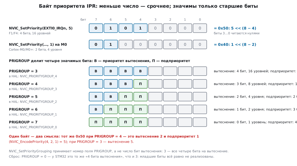
On STM32 4 bits — 16 levels are allotted to the priority, and a smaller number means a higher priority. Zero is the most urgent.
The four bits are divided into two parts:
- pre-emption priority — whether this interrupt can interrupt the one being executed;
- subpriority — which one to let in first if two events are waiting simultaneously and their pre-emption priority is the same.
The ratio is set by the grouping:
NVIC_SetPriorityGrouping(3);   /* PRIGROUP = 3: все 4 бита — вытеснение; в HAL это NVIC_PRIORITYGROUP_4 */
NVIC_SetPriority(EXTI0_IRQn, 5);
NVIC_EnableIRQ(EXTI0_IRQn);
The CMSIS function takes the number of the PRIGROUP field, not the number of pre-emption bits:
3 — four pre-emption bits, 4 — three pre-emption bits and one subpriority bit.
The constant NVIC_PRIORITYGROUP_4 (its value is 3) is declared in the HAL header,
and in a project with only CMSIS headers a line with it will not build.
Practical advice: do not assign priorities "by the importance of the task". Assign them by urgency of response. A handler that must finish within microseconds (timer capture, receiving a byte) gets a high priority; one where only the fact of the event matters (a button press) gets a low one.
⚠️ If you work under FreeRTOS, interrupts from which OS functions are called must have a priority numerically not less than the threshold (that is, logically not more urgent than it). The threshold is written twice in
FreeRTOSConfig.h:configLIBRARY_MAX_SYSCALL_INTERRUPT_PRIORITY(for example, 5) is the number forNVIC_SetPriority, andconfigMAX_SYSCALL_INTERRUPT_PRIORITYis the same number shifted into the upper bits of the priority byte:5 << 4=0x50. Violating this leads to rare and hard-to-reproduce failures. In detail — in section 28.
7.4 SysTick
The only timer built into the core itself rather than into ST's peripherals. That is why it exists on any Cortex-M, and code using it ports without changes.
SysTick_Config(SystemCoreClock / 1000u);   /* прерывание каждую миллисекунду */

volatile uint32_t ms_ticks = 0;

void SysTick_Handler(void)
{
    ms_ticks++;
}

void delay_ms(uint32_t ms)
{
    uint32_t start = ms_ticks;
    while ((ms_ticks - start) < ms) { }
}
HAL_Delay is built on it, and it is also what usually gives the tick to the RTOS
scheduler.
The subtraction
ms_ticks - startinstead of the comparisonms_ticks < start + msis chosen for a reason: unsigned arithmetic survives counter overflow correctly, while the comparison with a sum does not.
What SysTick_Config does. It is a few writes to core registers:
LOAD — the number to count down from (one less than the period), VAL —
the current value (any write clears the counter), CTRL — control:
ENABLE (bit 0) starts counting, TICKINT (bit 1) enables the interrupt on
passing through zero, CLKSOURCE (bit 2) takes the core clock rather than the clock divided by 8.
For 1 ms at 72 MHz the function writes LOAD = 71999 and CTRL = 7 — all three bits.
The counter is 24-bit. LOAD holds no more than 0xFFFFFF, that is,
a period no longer than 16 777 216 cycles: at 72 MHz this is 233 ms, at 168 MHz —
99.9 ms. A one-second tick cannot be obtained this way, and the function does not shout about it — it
simply returns 1 and enables nothing. In a run on a Cortex-M4 core with
the real SysTick_Config from CMSIS the number 16 777 216 passed, 16 777 217 and
72 000 000 returned 1, and CTRL stayed zero. The result is worth checking:
if (SysTick_Config(SystemCoreClock / 1000u) != 0u) {
    /* период не влез в 24 бита — SysTick не запущен */
}
The "SysTick" tab in the app's calculators does the same arithmetic:
the clock and the interrupt rate give LOAD, the actual period and the longest period
that fits into 24 bits at that clock.
COUNTFLAG is cleared by reading. Bit 16 of the CTRL register is set when
the counter has passed through zero, and is cleared when the program reads CTRL and on
a write to VAL. Two reads in a row in the run gave 1 and 0. A read by the debugger
usually does not touch the flag: the debug port marks its accesses with the
MasterType bit, and such a read does not clear COUNTFLAG. But any extra
program line that reads CTRL eats the flag.
7.5 EXTI: how a signal reaches the handler
External interrupts from pins pass through a separate block — the EXTI controller. The path consists of several stages, and skipping any of them means that the interrupt simply will not arrive.
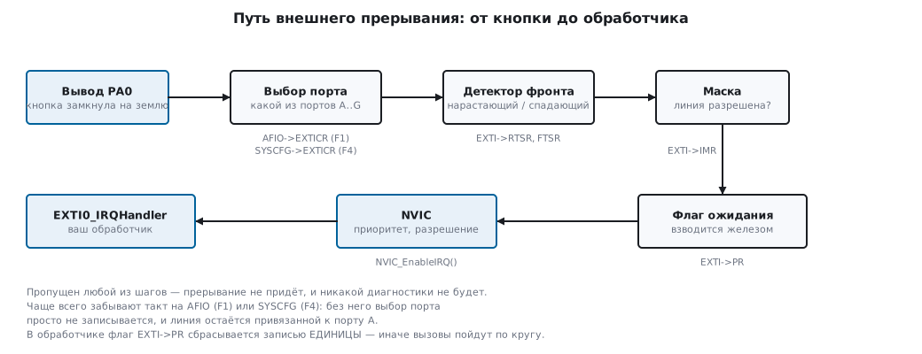
An important limitation. For pins EXTI has sixteen lines — matching the number
of pins in a port (the other lines are internal: PVD, RTC alarm, USB wake-up).
Line number n serves pin n of one of the ports: EXTI0 is
PA0, or PB0, or PC0, but not two at once.
The second feature is that there are fewer vectors than lines:
| Lines | Vector |
|---|---|
| 0, 1, 2, 3, 4 | each has its own: EXTI0_IRQn…EXTI4_IRQn |
| 5…9 | one shared: EXTI9_5_IRQn |
| 10…15 | one shared: EXTI15_10_IRQn |
In a shared handler you will have to find out which line fired by reading
the EXTI->PR flags.
Two outputs of one detector. An edge on a pin is caught by one circuit, but it has two outputs, and they are enabled by different registers:
| Register | Where the signal goes | What happens |
|---|---|---|
EXTI->IMR |
to the NVIC | the interrupt is queued, the core enters the handler |
EXTI->EMR |
straight to the core | the core receives an event: there is no handler, the program simply continues |
The bits are independent — both masks can be enabled at once: in the experiment below after
IMR |= 1 and EMR |= 1 both registers read as 0x00000001.
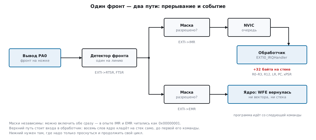
What a handler costs. Before entering it the core itself pushes
eight words onto the stack — R0–R3, R12, LR, the return address and xPSR. This can be seen right
in the program: main remembers the stack pointer, the handler its own, and the difference
comes to 32 bytes. Not a single handler instruction has been
executed at that point.
Why an event is needed. The core can wait with two instructions: WFI — until an
interrupt, WFE — until an event. An event wakes the core without opening a handler:
the program continues from the next instruction after WFE. No stack, no vector,
no flag clearing — so "wake up and continue your loop" is cheaper
than "enter the handler, exit and return to the same place".
The same effect by another path. An interrupt enabled in the NVIC but masked by
PRIMASK does not disappear: it stays pending. In the same experiment after
cpsid i the entry counter did not change — the handler did not run — and in
NVIC->ISPR bit 6 was lit (0x00000040), that is, the interrupt is waiting. After
cpsie i the handler was entered, the counter became 2, and the pending state cleared. A pending
interrupt wakes WFI even with PRIMASK set, and WFE only if
the SEVONPEND bit is raised in SCB->SCR (section 10.2): then every interrupt
that becomes pending counts as an event. This is used when you need to
wake up but handle it not immediately and in your own order.
| What is needed | How to do it |
|---|---|
| react to an edge with code | interrupt: IMR |
| wake up and continue your loop | event: EMR and WFE |
| wake up, but handle later and in your own order | an interrupt masked by PRIMASK, and WFI (or WFE with SEVONPEND) |
⚠️ A single
WFEis not a wait. The core has an "event happened" flag, and if it is already set, the instruction returns at once without waiting for anything. That is whyWFEis placed in a loop that checks the real condition — a flag, a counter, a queue — rather than assuming that the condition is necessarily met afterWFE.
7.6 🔧 Recipe: a button on an interrupt
The same task that was solved by polling in section 8 — now without a waiting loop.
STM32F103:
volatile uint8_t button_pressed = 0;   /* volatile обязателен */

void EXTI0_Config(void)
{
    /* Такт на порт A и на AFIO — без AFIO выбор линии не запишется. */
    RCC->APB2ENR |= RCC_APB2ENR_IOPAEN | RCC_APB2ENR_AFIOEN;

    /* PA0 — вход с подтяжкой вверх (у F1 направление задаётся битом в ODR). */
    GPIOA->CRL &= ~(GPIO_CRL_MODE0 | GPIO_CRL_CNF0);
    GPIOA->CRL |= GPIO_CRL_CNF0_1;
    GPIOA->ODR |= GPIO_ODR_ODR0;

    /* Привязка линии EXTI0 к порту A. */
    AFIO->EXTICR[0] &= ~AFIO_EXTICR1_EXTI0;
    AFIO->EXTICR[0] |= AFIO_EXTICR1_EXTI0_PA;

    /* Спадающий фронт: кнопка замыкает вывод на землю. */
    EXTI->IMR  |= EXTI_IMR_MR0;
    EXTI->FTSR |= EXTI_FTSR_TR0;
    EXTI->RTSR &= ~EXTI_RTSR_TR0;

    NVIC_SetPriority(EXTI0_IRQn, 5);
    NVIC_EnableIRQ(EXTI0_IRQn);
}

void EXTI0_IRQHandler(void)
{
    if (EXTI->PR & EXTI_PR_PR0) {
        EXTI->PR = EXTI_PR_PR0;      /* сброс флага — записью ЕДИНИЦЫ */
        button_pressed = 1;          /* вся работа — в основном цикле */
    }
}
STM32F407 — the difference is in two places:
    RCC->AHB1ENR |= RCC_AHB1ENR_GPIOAEN;     /* порты на AHB1, а не APB2 */
    RCC->APB2ENR |= RCC_APB2ENR_SYSCFGEN;    /* SYSCFG вместо AFIO */

    GPIOA->MODER &= ~GPIO_MODER_MODER0;
    GPIOA->PUPDR &= ~GPIO_PUPDR_PUPD0;
    GPIOA->PUPDR |= GPIO_PUPDR_PUPD0_0;      /* честный регистр подтяжек */

    SYSCFG->EXTICR[0] &= ~SYSCFG_EXTICR1_EXTI0;
    SYSCFG->EXTICR[0] |= SYSCFG_EXTICR1_EXTI0_PA;
The rest — masks, edges, NVIC, handler — is word for word the same.
⚠️ The most frequent mistake when porting from F1 to F4 is to remove the line with
AFIO(under F4 it will not even build: there is no such block) and not add theSYSCFGclock. Without it the write toEXTICRsimply does not go through. The line stays bound to port A by default: the button onPB0is silent, andPA0fires from noise.
7.7 What a handler should be like
Short. While a handler runs, everything else waits. The rule is simple: inside — only what cannot be postponed. Set a flag, put a byte into a buffer, toggle a pin — and leave. Parsing data, calculations, work with a display are done in the main loop.
Without delays. HAL_Delay inside a handler is a sure way to hang
the system: it itself waits for the SysTick interrupt, and that one may have a lower
priority and never get control.
Shared variables — only volatile. A flag that is set in a handler
and checked in main must be volatile, otherwise the compiler optimises away
the check (the analysis with assembly is in section 3).
The flag must be cleared. If you did not clear EXTI->PR, the handler will
be called right after exit, again and again, and the program will never
return to the main loop. And clearing is done by writing a one, not
a zero: writing a zero does nothing. The flag is cleared at the start of the handler,
not in the last line: the write reaches the peripheral in a few cycles, and if
the core exits earlier, the NVIC will see the same request and call the handler once more.
If the clearing does stand at the end, put __DSB() after it or read the
register back.
Atomicity. If the main code and the handler change the same variable,
volatile alone is not enough: counter++ consists of three operations, and an interrupt
can wedge in between. A critical section or an atomic operation is needed
(section 5).
7.8 F0 and G0: the Cortex-M0 and M0+ core
STM32F0 has a Cortex-M0 core, G0 a Cortex-M0+. The vectors, EXTI and the rules for handlers in this section hold for them too, but the core is simpler, and when porting code from F103 or F407 people run into the same differences:
| F1, F4 (M3, M4) | F0 (M0) | G0 (M0+) | |
|---|---|---|---|
| priority bits | 4 — 16 levels | 2 — 4 levels | 2 — 4 levels |
| subpriorities | yes | no | no |
BASEPRI |
yes | no | no |
table relocation, VTOR |
yes | no | yes |
UDIV division |
yes | no | no |
| port selection for a line | AFIO (F1), SYSCFG (F4) |
SYSCFG |
in EXTI itself |
| line flag | PR |
PR |
RPR1 — rising, FPR1 — falling |
Priorities. There are four levels, from 0 to 3, and there is no grouping into pre-emption
and subpriority at all. NVIC_SetPriority(EXTI0_1_IRQn, 1) writes 0x40 into the priority
byte: only the two upper bits are significant. A call to
NVIC_SetPriorityGrouping from F4 code will build but do nothing:
in the M0 core header it is an empty stub (void)(X).
A critical section — only all at once. BASEPRI, with which M3 and M4 mask
only the lower priorities, does not exist on M0 and M0+, and the compiler for F0 simply
does not know __set_BASEPRI. What remains is PRIMASK — switching off all interrupts at once:
uint32_t primask = __get_PRIMASK();
__disable_irq();
uint32_t n = presses;
presses = 0;
__set_PRIMASK(primask);
In the object file this is MRS PRIMASK, CPSID i and MSR PRIMASK — three instructions.
The FreeRTOS port for Cortex-M0 works the same way: in a critical section all interrupts
are masked, and the configMAX_SYSCALL_INTERRUPT_PRIORITY setting has no
effect on it.
Shared EXTI vectors. Lines 0 and 1 share the vector EXTI0_1_IRQn (5), 2 and 3 —
EXTI2_3_IRQn (6), and lines 4…15 — a single EXTI4_15_IRQn (7). In the handler of a
shared vector the flag of each line is checked.
F0: the port is selected in SYSCFG, as on F4. A button on PA0:
RCC->AHBENR |= RCC_AHBENR_GPIOAEN;                 /* порты у F0 — на AHB */
RCC->APB2ENR |= RCC_APB2ENR_SYSCFGCOMPEN;          /* такт SYSCFG — без него выбор порта не запишется */
SYSCFG->EXTICR[0] = (SYSCFG->EXTICR[0] & ~SYSCFG_EXTICR1_EXTI0) | SYSCFG_EXTICR1_EXTI0_PA;
EXTI->FTSR |= EXTI_FTSR_TR0;                       /* по спаду */
EXTI->IMR |= EXTI_IMR_MR0;
NVIC_SetPriority(EXTI0_1_IRQn, 1);                 /* уровни 0…3 */
G0: the port is selected in EXTI itself, and there are two flags. SYSCFG is not
needed for this; the port field is 3 bits, but they come every 8. Falling and rising edges are marked
in different registers, and the handler must look into the one that is enabled:
RCC->IOPENR |= RCC_IOPENR_GPIOAEN;                 /* порты у G0 — отдельный регистр IOPENR */
EXTI->EXTICR[0] &= ~EXTI_EXTICR1_EXTI0;            /* 0 — порт A; выбор порта живёт в EXTI */
EXTI->FTSR1 |= EXTI_FTSR1_FT0;
EXTI->IMR1 |= EXTI_IMR1_IM0;

void EXTI0_1_IRQHandler(void)
{
    if (EXTI->FPR1 & EXTI_FPR1_FPIF0) {                /* спад — свой регистр FPR1, фронт — RPR1 */
        EXTI->FPR1 = EXTI_FPR1_FPIF0;
        presses++;
    }
}
The vector table in RAM. On G0 (M0+) it is relocated by SCB->VTOR, as on F4.
F0 has no such register — SCB->VTOR does not build: "no member named
'VTOR'". A bootloader on F0 copies the table to the start of RAM and maps RAM
to address zero with the MEM_MODE bits in SYSCFG->CFGR1.
There is no division in hardware. sum / count on M0 and M0+ is a call to the library
__aeabi_uidiv, not a single UDIV instruction as on M3. In an interrupt
handler you divide by a power of two — with a shift.
7.9 Pitfalls
The interrupt does not arrive. Check along the chain: is the port clock enabled;
is the AFIO (F1) or SYSCFG (F4) clock enabled; is the line bound to the right
port; is the line unmasked in IMR; is the edge selected in RTSR/FTSR;
is the interrupt enabled in the NVIC. Skipping any step gives the same
result — silence.
The handler is called endlessly. Clearing the EXTI->PR flag is forgotten.
EXTI->PR |= EXTI_PR_PR0 loses other interrupts. The PR bits
are cleared by writing a one, and writing a zero does not touch them. The |= operator
first reads the whole register: if at that moment, say,
line 2 is also waiting, its bit is read as a one, written back as a one — and
the flag of line 2 is cleared, although its handler has not been called yet. The interrupt
vanishes without a trace. Clear with an assignment, only your own bit:
EXTI->PR = EXTI_PR_PR0;      /* верно: сбрасывается только линия 0 */
EXTI->PR |= EXTI_PR_PR0;     /* ошибка: сбрасываются все ждущие линии */
In the register model lines 0 and 2 are waiting: after |= the register holds 0x00,
after the assignment — 0x04, and line 2 waits for its handler.
In the documentation such bits are marked rc_w1 — "read, cleared
by writing one"; |= is never suitable for them.
Bounce turns into a dozen interrupts. A mechanical button gives a burst of pulses on an edge, and the handler will run on each one. The cure is the same as with polling: a software delay, checking the state after 10–20 ms, or an RC network (the circuit is in section 8).
HardFault. An access to a non-existent address, a wrong pointer or
a branch to an even address lead to the HardFault exception, and by default —
to an endless loop. Division by zero on M3 and M4 gives no exception: SDIV
and UDIV silently return 0 until the DIV_0_TRP bit is set (7б.7).
A stack overflow first quietly corrupts neighbouring variables (section 11),
and a fault occurs only when the stack pointer goes beyond RAM.
It is useful from the very start to write
your own handler that at least blinks an LED:
void HardFault_Handler(void)
{
    while (1) {
        GPIOC->ODR ^= GPIO_ODR_ODR13;
        for (volatile int i = 0; i < 200000; i++) { }
    }
}
This way you will tell "hung somewhere in the logic" from "fell into an exception" — finding the causes of a HardFault from the stack contents is covered in section 35.
A handler priority above the system one. A handler with priority 0 that
runs for a long time blocks SysTick — and HAL_Delay in the main code stops
counting time.
7.10 Summary
- An interrupt lets you avoid polling the hardware: the processor is busy with work, and the event comes by itself.
- A handler is bound by function name; a typo does not cause a compilation error, the interrupt simply goes to an empty stub.
- STM32 has 16 priority levels, a smaller number is more urgent. Assign them by the required response speed, not by the importance of the task.
- SysTick is built into the core and ports between any Cortex-M.
- There are sixteen EXTI lines, and line n serves pin n of only one port. Lines 5…9 and 10…15 share a vector.
- On F1 the port for a line is selected through
AFIO, on F4 throughSYSCFG; a clock for this block is mandatory. - The
EXTI->PRflag is cleared by writing a one. Otherwise the handler will loop. - In a handler — minimum work, no delays, shared variables
volatile. - F0 and G0: 4 priority levels, no
BASEPRIand no hardware division; F0 has noVTOR, on G0 the line's port is selected inEXTIitself, and the flags areRPR1andFPR1.
Full sources
irq_f0.c — button PA0 on an interrupt on STM32F072 (Cortex-M0).
/* Раздел 7.8: кнопка PA0 по прерыванию на STM32F072 (Cortex-M0).
 * Порт для линии EXTI выбирается в SYSCFG, как у F4; такт — SYSCFGCOMPEN. */
#include "stm32f0xx.h"

_Static_assert(__NVIC_PRIO_BITS == 2, "у Cortex-M0 два бита приоритета — 4 уровня");
_Static_assert(((1u << (8u - __NVIC_PRIO_BITS)) & 0xFFu) == 0x40u, "приоритет 1 — это 0x40 в байте IPR");
_Static_assert(EXTI0_1_IRQn == 5 && EXTI2_3_IRQn == 6 && EXTI4_15_IRQn == 7, "общие векторы EXTI");
_Static_assert(SYSCFG_EXTICR1_EXTI0 == 0xFu && SYSCFG_EXTICR1_EXTI0_PA == 0u, "порт — поле из 4 бит, A = 0");

volatile uint32_t presses;

void button_irq_init_f0(void)
{
    RCC->AHBENR |= RCC_AHBENR_GPIOAEN;                 /* порты у F0 — на AHB */
    RCC->APB2ENR |= RCC_APB2ENR_SYSCFGCOMPEN;          /* такт SYSCFG — без него выбор порта не запишется */
    GPIOA->PUPDR |= GPIO_PUPDR_PUPDR0_0;               /* подтяжка вверх, кнопка на землю */
    SYSCFG->EXTICR[0] = (SYSCFG->EXTICR[0] & ~SYSCFG_EXTICR1_EXTI0) | SYSCFG_EXTICR1_EXTI0_PA;
    EXTI->FTSR |= EXTI_FTSR_TR0;                       /* по спаду */
    EXTI->IMR |= EXTI_IMR_MR0;
    NVIC_SetPriority(EXTI0_1_IRQn, 1);                 /* уровни 0…3 */
    NVIC_EnableIRQ(EXTI0_1_IRQn);
}

void EXTI0_1_IRQHandler(void)                          /* один вектор на линии 0 и 1 */
{
    if (EXTI->PR & EXTI_PR_PR0) {
        EXTI->PR = EXTI_PR_PR0;                        /* сброс записью единицы */
        presses++;
    }
}

/* Критическая секция: BASEPRI у Cortex-M0 нет — только PRIMASK, то есть все прерывания сразу. */
uint32_t take_presses(void)
{
    uint32_t primask = __get_PRIMASK();
    __disable_irq();
    uint32_t n = presses;
    presses = 0;
    __set_PRIMASK(primask);
    return n;
}

/* Деление: у Cortex-M0 и M0+ нет команды UDIV — компилятор зовёт библиотечную функцию. */
uint32_t average(uint32_t sum, uint32_t count)
{
    return sum / count;
}
irq_g0.c — button PA0 on an interrupt on STM32G071 (Cortex-M0+).
/* Раздел 7.8: кнопка PA0 по прерыванию на STM32G071 (Cortex-M0+).
 * Порт выбирается в самом EXTI, SYSCFG не нужен; флаги спада и фронта раздельные. */
#include "stm32g0xx.h"

_Static_assert(__NVIC_PRIO_BITS == 2 && __VTOR_PRESENT == 1, "M0+: 4 уровня приоритета, но VTOR есть");
_Static_assert(EXTI0_1_IRQn == 5 && EXTI2_3_IRQn == 6 && EXTI4_15_IRQn == 7, "общие векторы EXTI — как у F0");
_Static_assert(EXTI_EXTICR1_EXTI0 == 0x7u && EXTI_EXTICR1_EXTI1_Pos == 8u, "порт — поле из 3 бит через каждые 8");

volatile uint32_t presses;

void button_irq_init_g0(void)
{
    RCC->IOPENR |= RCC_IOPENR_GPIOAEN;                 /* порты у G0 — отдельный регистр IOPENR */
    GPIOA->PUPDR |= GPIO_PUPDR_PUPD0_0;
    EXTI->EXTICR[0] &= ~EXTI_EXTICR1_EXTI0;            /* 0 — порт A; выбор порта живёт в EXTI */
    EXTI->FTSR1 |= EXTI_FTSR1_FT0;
    EXTI->IMR1 |= EXTI_IMR1_IM0;
    NVIC_SetPriority(EXTI0_1_IRQn, 1);
    NVIC_EnableIRQ(EXTI0_1_IRQn);
}

void EXTI0_1_IRQHandler(void)
{
    if (EXTI->FPR1 & EXTI_FPR1_FPIF0) {                /* спад — свой регистр FPR1, фронт — RPR1 */
        EXTI->FPR1 = EXTI_FPR1_FPIF0;
        presses++;
    }
}

/* У M0+ таблицу векторов можно перенести в ОЗУ регистром VTOR — как у M3/M4. */
void vectors_to_ram(const uint32_t *table)
{
    SCB->VTOR = (uint32_t)table;
}
Next: section 7а "Exception entry from the inside: the stack frame, EXC_RETURN and the FPU".