 Embedded HandbookApps
153. GPIO and PWM on ESP32: pins, electrical limits, strapping, the signal matrix, LEDC, MCPWM
An STM32 pin from section 8 is port registers, an alternate function
from a table and a current of up to 20 mA. On ESP32 everything means the same and is built
differently: the pin numbers have gaps, six of them are taken by
the flash memory, six can only listen, five decide the fate of the
chip at reset, and almost any peripheral signal can be routed to almost any pin through
the matrix. PWM here is two different blocks: LEDC for LEDs and
regulators, MCPWM for motors. The section rests on three sources:
a program in QEMU (_verify/esp153/), the ESP-IDF headers and the tables of
the ESP32 datasheet version 5.3 (the excerpt datasheet_dc.txt); the analog
part — PWM through an RC filter — is computed by ngspice.
Terms used in the documentation
Term Meaning GPIO pad the pin's contact pad with its own buffer IO_MUX the pin multiplexer: a direct path to the pin's "native" function GPIO matrix the matrix: any peripheral signal to any pin input-only pins pins that are inputs only (34–39), without pull-ups strapping pins pins latched at reset (0, 2, 5, 12, 15) drive strength (drive capability) output strength: four current steps VIH / VIL, VOH / VOL input thresholds, output levels IOH / IOL output current at high and at low LEDC (LED PWM controller) a general-purpose PWM controller duty resolution, hpoint duty cycle resolution, the switch-on point within the period high-speed / low-speed mode two LEDC blocks: with hardware and with software update MCPWM (motor control PWM) PWM for motors: output pairs, dead time, protection operator, generator, comparator the MCPWM operator, generator, comparator
153.1 Pin numbers: where the gaps are
The program walks through the numbers with the driver macros:
    for (int i = 0; i < SOC_GPIO_PIN_COUNT; i++) {
        valid += GPIO_IS_VALID_GPIO(i);
        outputs += GPIO_IS_VALID_OUTPUT_GPIO(i);
    }
номеров GPIO 40, из них существуют 35, с выходом 29
нет на кристалле: 24 28 29 30 31
только вход: 34 35 36 37 38 39
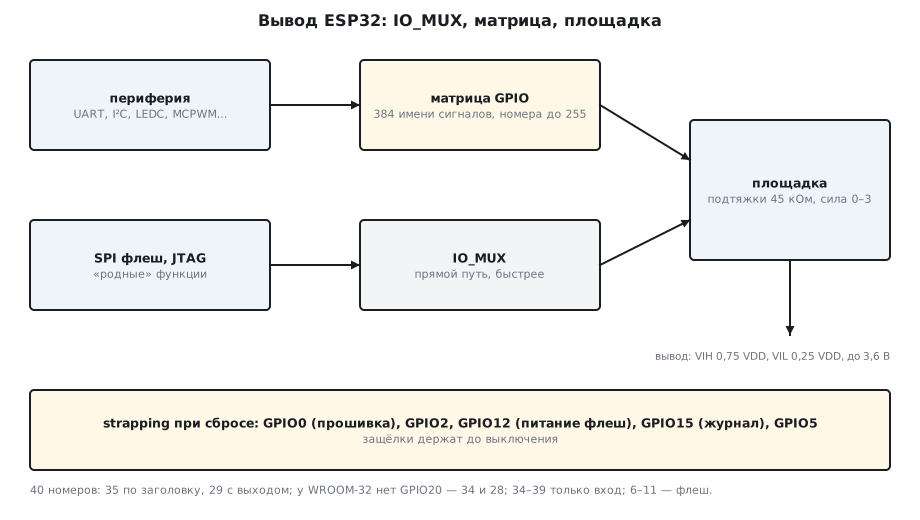
There are 40 numbers, 35 exist: 24 and 28–31 are not on the die. According to the header, GPIO20 exists, but it is brought out only on some packages, for example ESP32-PICO-V3; the ordinary chip and the WROOM-32 module do not have it — there are 34 pins, 28 of them with an output. The last six are inputs only, and they have no pull-ups: a button on GPIO34 needs an external resistor. Another six, 6–11, exist and can be outputs, but on the module the flash memory is soldered to them (section 150) — the driver does not forbid them, but a program that touches them stops reading its own code. The driver checks only what it knows:
GPIO2  как выход: ESP_OK
GPIO34 как выход: ESP_ERR_INVALID_ARG
GPIO24 как выход: ESP_ERR_INVALID_ARG
So for a product on WROOM-32 you are left with 28 outputs minus 6 for the flash memory minus the strapping pins, which must not be disturbed at reset — about two dozen free ones.
153.2 Pin electrical characteristics: the datasheet numbers
Table 5-3 of the datasheet (3.3 V, 25 °C):
| Parameter | Value | What it means |
|---|---|---|
| VIH | ≥ 0.75 × VDD = 2.475 V | the input high threshold |
| VIL | ≤ 0.25 × VDD = 0.825 V | the low threshold |
| input, maximum | VDD + 0.3 = 3.6 V | no 5 V on an input |
| VOH / VOL | ≥ 0.8 × VDD / ≤ 0.1 × VDD | output levels |
| IOH | 40 mA at VOH ≥ 2.64 V, output strength at maximum | the "high" current from one pin |
| IOL | 28 mA at VOL = 0.495 V | the "low" current |
| RPU / RPD | 45 kΩ | internal pull-ups and pull-downs |
| CIN | 2 pF | pin capacitance |
| IIH / IIL | 50 nA | input leakage current |
Two caveats from the same table. First, 40 mA is at the maximum
output strength, and by default it is medium: there are four steps, from 0
(weak) to 3, with 2 as the default (GPIO_DRIVE_CAP_DEFAULT in the header).
The program sets step 3 and reads it back — in the emulator it gets
0, because the emulator has no pin registers (153.8), while on a board it reads 3:
сила выхода GPIO2: 0 (ступени 0..3, по умолчанию 2)
Second, 40 mA is from one pin; the more pins in one power domain source current at the same time, the less each one gets: the datasheet gives a drop to about 29 mA. For the outputs of the VDD_SDIO domain (the flash memory pins) the limit is 20 mA. The rule is the same as in section 62: do not hang on the pins what you can hang on a transistor.
The 45 kΩ pull-ups are weak: they are no good for I²C (section 95 asks for 1.5–4.7 kΩ), and for a button in a noisy place external 10 kΩ ones are better too.
153.3 Strapping: five pins at reset
At reset the chip latches the levels of five pins and uses them to decide how to boot (table 3-1 of the datasheet):
| Pin | Internal pull | Default bit | What it controls |
|---|---|---|---|
| GPIO0 | up | 1 | 1 — boot from flash memory, 0 — download mode |
| GPIO2 | down | 0 | together with GPIO0 = 0 selects download over UART |
| MTDI (GPIO12) | down | 0 | flash memory supply voltage: 0 — 3.3 V, 1 — 1.8 V |
| MTDO (GPIO15) | up | 1 | printing of the ROM log to UART0 at startup |
| GPIO5 | up | 1 | SDIO slave timing |
Boot from flash memory happens with GPIO0 = 1 regardless of GPIO2; download
mode is GPIO0 = 0 and GPIO2 = 0 (table 3-3). Hence the two buttons
of the DevKit: EN pulls reset, BOOT pulls GPIO0 to ground. The latches
hold their values until power-off, and after reset the pins are free
— but whatever hangs on them outside must not pull the level at the
moment of reset. The most treacherous one is GPIO12: pulled up by a sensor, it
switches the flash memory supply to 1.8 V, and a module with a 3.3 V
chip will not boot at all. If you still need GPIO12 with a pull-up,
the flash memory voltage is fixed in eFuse: espefuse.py set_flash_voltage 3.3V.
This is irreversible, and after it the level of GPIO12 is not read at reset.
153.4 IO_MUX and the matrix
Every pin has several "native" functions through IO_MUX — this is how
the flash memory and SPI are connected on their own pins, and it is the fastest path.
Everything else goes through the GPIO matrix: the peripherals have numbered
signals — the header gpio_sig_map.h has 384 names with numbers up to 255, and
256 means "plain GPIO" — and any of them can be assigned to almost
any pin:
имён сигналов в gpio_sig_map.h: 384, наибольший номер: 256, SIG_GPIO_OUT_IDX 256
U0RXD_IN_IDX 14
U0TXD_OUT_IDX 14
SPICLK_OUT_IDX 0
I2CEXT0_SCL_IN_IDX 29
LEDC_HS_SIG_OUT0_IDX 71
PWM0_OUT0A_IDX 32
The drivers do this themselves: ledc_channel_config with gpio_num = 2
connects the signal LEDC_HS_SIG_OUT0 to pin 2 through the matrix, and
moving UART, I²C or PWM to other pins is a matter of one
number in a structure, not of an alternate function table. The price of the matrix is
extra delay and a frequency limit: SPI through the matrix is slower than
through IO_MUX, and for 40–80 MHz you choose the native pins.
153.5 LEDC: frequency versus resolution
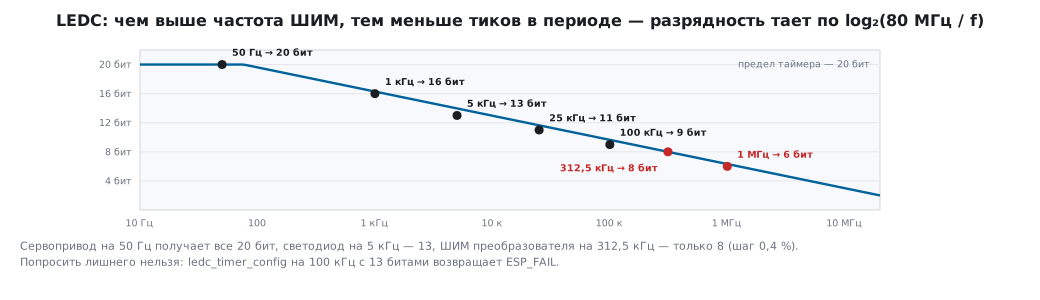
LEDC has 16 channels: two modes with 8 channels and 4 timers each, a timer of up to 20 bits, an 80 MHz clock. The duty cycle is set in timer ticks, and the higher the PWM frequency, the fewer ticks in a period — resolution and frequency trade against each other by the formula f_max = 80 MHz / 2^bits. The driver computes this itself:
    for (size_t i = 0; i < sizeof freqs / sizeof freqs[0]; i++) {
        uint32_t bits = ledc_find_suitable_duty_resolution(80000000, freqs[i]);
       50 Гц: до 20 бит (шаг 0.0001 %)
     1000 Гц: до 16 бит (шаг 0.0015 %)
     5000 Гц: до 13 бит (шаг 0.0122 %)
    25000 Гц: до 11 бит (шаг 0.0488 %)
   100000 Гц: до  9 бит (шаг 0.1953 %)
   312500 Гц: до  8 бит (шаг 0.3906 %)
  1000000 Гц: до  6 бит (шаг 1.5625 %)
A servo at 50 Hz gets all 20 bits, an LED at 5 kHz gets 13, and PWM at 312.5 kHz that feeds a converter gets only 8, that is a step of 0.4 %. You cannot ask for more:
ledc_timer_config 5 кГц / 13 бит: ESP_OK
ledc_timer_config 100 кГц / 13 бит: ESP_FAIL
Setup is two calls, the timer and the channel:
    ledc_timer_config_t tc = { .speed_mode = LEDC_HIGH_SPEED_MODE, .timer_num = LEDC_TIMER_0, .duty_resolution = LEDC_TIMER_13_BIT,
                               .freq_hz = 5000, .clk_cfg = LEDC_AUTO_CLK };
    ledc_channel_config_t cc = { .gpio_num = 2, .speed_mode = LEDC_HIGH_SPEED_MODE, .channel = LEDC_CHANNEL_0, .timer_sel = LEDC_TIMER_0,
                                 .duty = 4096, .hpoint = 0 };
A duty of 4096 out of 8192 is 50 %. Then come ledc_set_duty and
ledc_update_duty: the first prepares the value, the second applies it —
which is why a forgotten update is the most common mistake with LEDC. The
high-speed mode updates the duty in hardware at the period boundary, low-speed
does it in software; the latter has its own clock generator that runs in
light sleep. The hardware fade ledc_fade brings the
duty to the target in a given time without the CPU.
153.6 PWM as a DAC: the price of frequency
The same timer gives either precision or frequency, and an RC filter shows it. ngspice: 3.3 V, 50 % duty, a 10 kΩ / 100 nF filter (time constant 1 ms), three pairs from one timer:
f=1k ripple_V=0.808228
f=5k ripple_V=0.164858
f=312.5k ripple_V=0.002636
The peak-to-peak ripple at 50 % is U · tanh(1/(4·f·RC)), and that is what ngspice computes. 16 bits at 1 kHz give a ripple of 0.81 V — half the scale, no precision at all; 13 bits at 5 kHz give 0.16 V; 8 bits at 312.5 kHz give 2.6 mV, but the duty step of 0.4 % is the same 13 mV. The compromise for the PWM DAC from section 50 on ESP32 looks like this: 10–12 bits at 20–80 kHz and a second-order filter.
153.7 MCPWM: PWM for motors
The second block is MCPWM, two identical units:
SOC_MCPWM_GROUPS (2)
SOC_MCPWM_TIMERS_PER_GROUP (3)
SOC_MCPWM_OPERATORS_PER_GROUP (3)
SOC_MCPWM_COMPARATORS_PER_OPERATOR (2)
SOC_MCPWM_GENERATORS_PER_OPERATOR (2)
SOC_MCPWM_GPIO_FAULTS_PER_GROUP (3)
SOC_MCPWM_CAPTURE_TIMERS_PER_GROUP (1)
Each unit has three timers, three operators with two generators each — 12 outputs per chip, in A/B pairs for the high-side and low-side switch of a half bridge with dead time, three fault inputs that shut the outputs down in hardware, and a capture timer for Hall sensors and an encoder. This is what on STM32 is done by the TIM1 timer with complementary outputs (section 13): a bridge, a three-phase motor, a synchronous rectifier. For an LED and a servo MCPWM is overkill — use LEDC there.
153.8 What the emulator cannot do
GPIO2: записали 1 — читаем 0, записали 0 — читаем 0
ledc_get_freq: 5000 Гц, ledc_get_duty: 0
On silicon a pin in INPUT_OUTPUT mode reads its own level
— here it reads zero; a duty just written to a channel reads back as
zero. QEMU for ESP32 has no model of the pins and LEDC: the registers are written into
the void. Everything above is a check of the driver logic and the arithmetic; levels
and waveforms are checked on a board. This is the emulator's boundary, and it is useful
to know it in advance so you do not hunt in your code for a bug that is not there.
153.9 Pitfalls
| Symptom | Cause |
|---|---|
gpio_set_direction returned ESP_ERR_INVALID_ARG |
pins 34–39 are inputs only, or the number does not exist on the die |
| a button on GPIO34 "floats" | 34–39 have no internal pull-ups |
the board reboots after gpio_config on GPIO6–11 |
these are the flash memory pins |
| the board does not start with peripherals connected | something pulls a strapping pin at reset; GPIO12 high = 1.8 V on the flash |
| the output "cannot drive" an LED with a 30 Ω resistor | output strength is 2 of 3, and 40 mA only at VOH ≥ 2.64 V |
| a 5 V sensor burned the input | the input takes up to VDD + 0.3 = 3.6 V |
ledc_timer_config → ESP_FAIL |
frequency × 2^bits is above 80 MHz |
ledc_set_duty changes nothing |
ledc_update_duty is forgotten |
| the PWM DAC is noisy | low frequency for the sake of resolution; raise the frequency, use a 2nd-order filter |
| SPI through the matrix does not reach 80 MHz | use the native IO_MUX pins |
| in the emulator GPIO reads as zero | QEMU does not model the pins |
153.10 Summary
- 40 numbers, 35 exist, 29 with an output; no 24, 28–31; GPIO20 is not in every package (WROOM-32 has 34 pins, 28 with an output); 34–39 are inputs only without pull-ups; 6–11 are the flash.
- Datasheet: VIH 0.75 VDD, VIL 0.25 VDD, input up to 3.6 V, IOH 40 mA (maximum strength, one pin), IOL 28 mA, pull-ups 45 kΩ; output strength 0–3, default 2.
- Strapping: GPIO0 = 0 — download mode; GPIO12 = 1 — flash at 1.8 V; GPIO15 — the ROM log.
- Matrix: 384 signal names with numbers up to 255 to any pin; IO_MUX is the direct path.
- LEDC: 16 channels, f_max = 80 MHz / 2^bits: 50 Hz — 20 bits, 5 kHz — 13, 312.5 kHz — 8;
set_duty+update_duty. - PWM through a 1 ms RC: 0.81 V of ripple at 1 kHz, 0.16 V at 5 kHz, 2.6 mV at 312.5 kHz.
- MCPWM: 2 × 3 operators × 2 generators = 12 outputs, dead time, fault inputs.
Full sources
main.c — GPIO and LEDC PWM on ESP32: what the driver allows.
/* Раздел 153: GPIO и ШИМ LEDC на ESP32 — что разрешает драйвер, что считает сам. */
#include <stdio.h>
#include "driver/gpio.h"
#include "driver/ledc.h"
#include "esp_err.h"
#include "esp_log.h"
#include "freertos/FreeRTOS.h"
#include "freertos/task.h"
#include "soc/gpio_num.h"
#include "soc/soc_caps.h"

static const char *TAG = "gpio153";

static void try_output(int pin)
{
    esp_err_t e = gpio_set_direction(pin, GPIO_MODE_OUTPUT);
    printf("GPIO%-2d как выход: %s\n", pin, esp_err_to_name(e));
}

void app_main(void)
{
    /* какие номера вообще существуют и какие умеют быть выходом — по маскам soc_caps */
    int valid = 0, outputs = 0;
    for (int i = 0; i < SOC_GPIO_PIN_COUNT; i++) {
        valid += GPIO_IS_VALID_GPIO(i);
        outputs += GPIO_IS_VALID_OUTPUT_GPIO(i);
    }
    printf("номеров GPIO %d, из них существуют %d, с выходом %d\n", SOC_GPIO_PIN_COUNT, valid, outputs);
    printf("нет на кристалле:");
    for (int i = 0; i < SOC_GPIO_PIN_COUNT; i++)
        if (!GPIO_IS_VALID_GPIO(i)) printf(" %d", i);
    printf("\nтолько вход:");
    for (int i = 0; i < SOC_GPIO_PIN_COUNT; i++)
        if (GPIO_IS_VALID_GPIO(i) && !GPIO_IS_VALID_OUTPUT_GPIO(i)) printf(" %d", i);
    printf("\n");

    esp_log_level_set("gpio", ESP_LOG_NONE);        /* драйвер и так вернёт код ошибки */
    try_output(2);
    try_output(34);
    try_output(24);

    /* выход с обратным чтением: режим INPUT_OUTPUT читает свой же уровень */
    gpio_config_t io = { .pin_bit_mask = 1ULL << 2, .mode = GPIO_MODE_INPUT_OUTPUT, .pull_up_en = 0, .pull_down_en = 0, .intr_type = GPIO_INTR_DISABLE };
    ESP_ERROR_CHECK(gpio_config(&io));
    gpio_set_level(2, 1);
    int a = gpio_get_level(2);
    gpio_set_level(2, 0);
    int b = gpio_get_level(2);
    printf("GPIO2: записали 1 — читаем %d, записали 0 — читаем %d\n", a, b);

    /* сила выхода: четыре ступени */
    gpio_drive_cap_t cap;
    gpio_set_drive_capability(2, GPIO_DRIVE_CAP_3);
    gpio_get_drive_capability(2, &cap);
    printf("сила выхода GPIO2: %d (ступени 0..%d, по умолчанию %d)\n", (int)cap, (int)GPIO_DRIVE_CAP_MAX - 1, (int)GPIO_DRIVE_CAP_DEFAULT);

    /* LEDC: сколько бит разрешения вмещает частота при тактировании 80 МГц */
    printf("LEDC: каналов %d × 2 режима, таймер до %d бит\n", SOC_LEDC_CHANNEL_NUM, SOC_LEDC_TIMER_BIT_WIDTH);
    const uint32_t freqs[] = { 50, 1000, 5000, 25000, 100000, 312500, 1000000 };
    for (size_t i = 0; i < sizeof freqs / sizeof freqs[0]; i++) {
        uint32_t bits = ledc_find_suitable_duty_resolution(80000000, freqs[i]);
        printf("  %7lu Гц: до %2lu бит (шаг %.4f %%)\n", (unsigned long)freqs[i], (unsigned long)bits, bits ? 100.0 / (1u << bits) : 0.0);
    }
    ledc_timer_config_t tc = { .speed_mode = LEDC_HIGH_SPEED_MODE, .timer_num = LEDC_TIMER_0, .duty_resolution = LEDC_TIMER_13_BIT,
                               .freq_hz = 5000, .clk_cfg = LEDC_AUTO_CLK };
    printf("ledc_timer_config 5 кГц / 13 бит: %s\n", esp_err_to_name(ledc_timer_config(&tc)));
    tc.freq_hz = 100000;
    printf("ledc_timer_config 100 кГц / 13 бит: %s\n", esp_err_to_name(ledc_timer_config(&tc)));
    tc.freq_hz = 5000;
    ledc_timer_config(&tc);
    ledc_channel_config_t cc = { .gpio_num = 2, .speed_mode = LEDC_HIGH_SPEED_MODE, .channel = LEDC_CHANNEL_0, .timer_sel = LEDC_TIMER_0,
                                 .duty = 4096, .hpoint = 0 };
    printf("ledc_channel_config GPIO2, скважность 4096/8192: %s\n", esp_err_to_name(ledc_channel_config(&cc)));
    printf("ledc_get_freq: %lu Гц, ledc_get_duty: %lu\n", (unsigned long)ledc_get_freq(LEDC_HIGH_SPEED_MODE, LEDC_TIMER_0),
           (unsigned long)ledc_get_duty(LEDC_HIGH_SPEED_MODE, LEDC_CHANNEL_0));
    ESP_LOGI(TAG, "done");
}
Next: section 154 — the ESP32 ADC and DAC.