 Embedded HandbookApps
154. ESP32 ADC and DAC: attenuation, calibration, ADC2 and Wi-Fi, continuous mode, DAC and cosine
The STM32 ADC from section 14 is 12 bits, the reference equals the supply, the accuracy is
on the order of one LSB, and the formula "code × 3.3 / 4096" works. The ESP32
ADC is also 12 bits and also successive approximation, but its reference is
internal and different on every die, the input does not cover the whole
supply range, and the linearity is such that without calibration the error
is measured in tens of millivolts. Hence everything in this section: four
attenuation windows, calibration from eFuse, a second ADC that goes off
together with Wi-Fi, and two eight-bit DACs with a cosine generator. The driver
logic is checked by QEMU (_verify/esp154/), the numbers by the datasheet (the excerpt
datasheet_adc.txt) and the ESP-IDF headers, the arithmetic by a Python model.
Terms used in the documentation
Term Meaning SAR ADC successive approximation ADC attenuation (0 / 2.5 / 6 / 12 dB) input attenuation: widens the measured window effective measurement range the window where accuracy is promised calibration, line fitting, two point calibration: along a line or by two points Vref, eFuse Vref the ADC reference and its value written to eFuse DNL, INL differential and integral nonlinearity total error the full error after calibration oneshot / continuous mode a single read / a stream through DMA RTC controller / DIG controller the ADC controller for single reads / for streaming conversion frame a frame of DMA results DAC, cosine wave generator the DAC, the cosine generator
154.1 Two blocks, 18 channels, and where they are
ADC1: ch0=GPIO36 ch1=GPIO37 ch2=GPIO38 ch3=GPIO39 ch4=GPIO32 ch5=GPIO33 ch6=GPIO34 ch7=GPIO35
ADC2: ch0=GPIO4 ch1=GPIO0 ch2=GPIO2 ch3=GPIO15 ch4=GPIO13 ch5=GPIO12 ch6=GPIO14 ch7=GPIO27 ch8=GPIO25 ch9=GPIO26
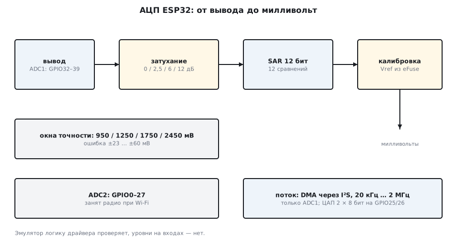
The channels are tied to the pins rigidly — the GPIO matrix from section 153 does not extend to analog signals. ADC1 sits on inputs 32–39: six of them are inputs only, which is just what an ADC needs. ADC2 is scattered over pins 0–27, among them three strapping pins (0, 2, 15) and both DAC outputs (25, 26). And most importantly: ADC2 does not work while Wi-Fi is on — the radio uses the same block to measure its own power. For a product with Wi-Fi you are left with ADC1: the bare chip has eight channels, and the WROOM-32 module has six (GPIO32–36 and 39): pins 37 and 38 are not on the module.
154.2 Attenuation: four windows
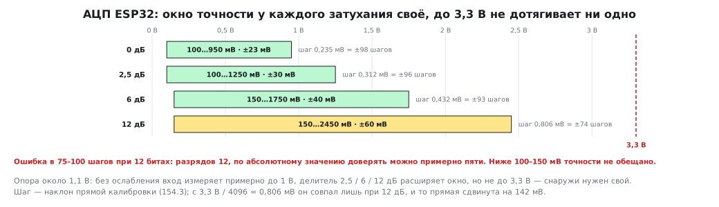
The ADC reference is about 1.1 V inside the chip, and without attenuation the input measures up to roughly 1 V. To measure up to 3.3 V, a divider with an attenuation of 2.5, 6 or 12 dB is placed in front of the ADC. The datasheet (table 4-4) promises accuracy only inside the windows:
| Attenuation | Window | Total error after calibration |
|---|---|---|
| 0 dB | 100 … 950 mV | ±23 mV |
| 2.5 dB | 100 … 1250 mV | ±30 mV |
| 6 dB | 150 … 1750 mV | ±40 mV |
| 12 dB | 150 … 2450 mV | ±60 mV |
Below 100–150 mV and above the upper limit the ADC works, but no accuracy is promised; at 12 dB above code 3000 (about 2450 mV) it is noticeably worse — this is a separate note of table 4-3. So ESP32 does not measure "3.3 V at the input" at all: an external divider is needed too. The nonlinearity per the same table is DNL up to ±7 and INL up to ±12 LSB, which is why averaging several samples is recommended. Each window has its own quantization step — it is the slope of the calibration line from 154.3 over codes 0…2048 (at 12 dB above code 2880 the driver switches to a table, and the curve bends). The accuracy window is narrower than the full code range, so you cannot divide the window by 4096:
3,3 В / 4096 = 0.806 мВ — так считать нельзя: шаг у окон разный, а прямая не проходит через ноль
0 дБ    окно  100… 950 мВ: шаг 0.235 мВ, ошибка после калибровки ±23 мВ = ±98 шагов
2,5 дБ  окно  100…1250 мВ: шаг 0.312 мВ, ошибка после калибровки ±30 мВ = ±96 шагов
6 дБ    окно  150…1750 мВ: шаг 0.432 мВ, ошибка после калибровки ±40 мВ = ±93 шагов
12 дБ   окно  150…2450 мВ: шаг 0.806 мВ, ошибка после калибровки ±60 мВ = ±74 шагов
At 12 dB the step coincides with 3.3 V / 4096, but the line is offset by 142 mV, so the formula "code × 0.806" lies there too.
An error of 75–100 steps at 12 bits means: there are 12 bits, but more than
six of them are eaten by the error, and in absolute terms you can trust
about five — that is ±2.5…2.7 % of the window. For a thermistor and a potentiometer this is
enough, for a voltmeter it is not; there you use an external ADC over
I²C or SPI. In ESP-IDF 5 the 11 dB attenuation is renamed to
12 dB, the old name ADC_ATTEN_DB_11 is marked deprecated and means the
same thing.
154.3 Calibration: code → millivolts
Every die has its own reference, and at the factory it is measured and written to eFuse. The calibration driver reads eFuse and builds a code → voltage line; if eFuse is empty, it takes 1100 mV:
        adc_cali_line_fitting_config_t cfg = { .unit_id = ADC_UNIT_1, .atten = att, .bitwidth = ADC_BITWIDTH_12, .default_vref = 1100 };
        adc_cali_handle_t h = NULL;
        esp_err_t e = adc_cali_create_scheme_line_fitting(&cfg, &h);
калибровка 0 дБ ESP_OK:    0→  75 мВ 1000→ 310 мВ 2048→ 557 мВ 3000→ 781 мВ 4095→1039 мВ
калибровка 2,5 дБ ESP_OK:    0→  78 мВ 1000→ 390 мВ 2048→ 718 мВ 3000→1015 мВ 4095→1357 мВ
калибровка 6 дБ ESP_OK:    0→ 107 мВ 1000→ 539 мВ 2048→ 992 мВ 3000→1404 мВ 4095→1877 мВ
калибровка 12 дБ ESP_OK:    0→ 142 мВ 1000→ 948 мВ 2048→1792 мВ 3000→2543 мВ 4095→3134 мВ
eFuse калибровки: нет — Vref по умолчанию 1100 мВ
The line does not pass through zero: code 0 at 12 dB is already 142 mV, and
4095 is 3134 mV. This is how the driver accounts for the ADC offset and slope; your own
formula "code × step" would give an error of hundreds of millivolts. The full
12 dB range reaches 3.1 V, but the promised accuracy ends at
2450 mV. adc_cali_raw_to_voltage is the only correct way
to get volts; adc_cali_scheme_line_fitting_check_efuse tells you
whether Vref or two points are written. In the emulator eFuse is empty, and the answer is "none".
154.4 Single read and streaming
A single read is three calls: adc_oneshot_new_unit,
adc_oneshot_config_channel with attenuation and bit width,
adc_oneshot_read. The first two pass in the emulator, the third does not:
adc_oneshot: блок и канал ADC1 ch6 (GPIO34) настроены; чтение ждёт флага готовности, которого в эмуляторе нет
QEMU does not model the ADC: the read waits for the "ready" flag forever, and after 300 ms the interrupt watchdog fires (section 152). So levels are checked only on a board, and everything else is checked in the emulator.
Continuous mode drives samples through DMA without the CPU — on ESP32 through the I²S controller, hence its limits:
непрерывный режим: 20000 … 2000000 Гц, 9…12 бит, кадр результата 2 байта
adc_continuous_config 10 кГц: ESP_ERR_INVALID_ARG
adc_continuous_config 20 кГц: ESP_OK
adc_continuous_config 2 МГц: ESP_OK
adc_continuous_config ADC2: ESP_ERR_INVALID_ARG
A stream cannot be slower than 20 kHz: if you want 1 kHz, you read single samples on a timer. Faster than 2 MHz is not possible either, and at 2 MHz it is 4 MB/s:
  20000 Гц × 2 байта = 40000 байт/с, кадр 256 байт — раз в 6.40 мс
2000000 Гц × 2 байта = 4000000 байт/с, кадр 256 байт — раз в 0.06 мс
A 256-byte frame at 2 MHz completes every 64 µs — the handler
must keep up. ADC2 cannot be used for streaming at all (ESP_ERR_INVALID_ARG):
only the first block has DMA. The datasheet gives the limits: 200 ksps
through the RTC controller (single reads) and 2 Msps through the digital one.
154.5 What the ADC does in 12 steps
Successive approximation is 12 comparisons, one per bit: a Python model for an input of 1730 mV with a nominal reference of 2450 mV:
шаг  1: пробуем 2048 ( 1225.0 мВ) — оставляем
шаг  2: пробуем 3072 ( 1837.5 мВ) — сбрасываем
шаг  3: пробуем 2560 ( 1531.2 мВ) — оставляем
шаг 12: пробуем 2893 ( 1730.4 мВ) — сбрасываем
код 2892 = 0b101101001100, 1729.8 мВ, ошибка 0.17 мВ
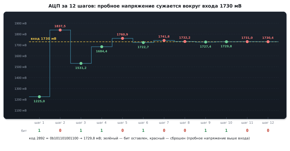
Each step sets the next bit, compares with the input and keeps or clears it; 12 steps are 12 ADC clock cycles, hence the speed limit. For an input of 1730 mV the error is 0.17 mV, 0.28 of a step (the step is 0.598 mV). An ideal ADC that, as here, discards the remainder errs by zero to one step, and the spread of the error over many inputs is step/√12 ≈ 0.29 of a step; a real one, as seen from 154.2, errs by almost a hundred steps. The ideal limit of the signal-to-noise ratio is 6.02·N + 1.76 dB:
 8 бит: SNR = 49.92 дБ
12 бит: SNR = 74.00 дБ
154.6 DAC: two channels and a cosine
dac_oneshot_output_voltage 128 (половина VDD): ESP_OK
dac_cosine 100 Гц: ESP_ERR_NOT_SUPPORTED
dac_cosine 1000 Гц: ESP_OK
Two 8-bit DACs on GPIO25 and GPIO26 — a resistor string with a buffer,
the reference is the supply, so the step is 3.3 V / 256 ≈ 13 mV and there is no accuracy
better than a percent. Three modes: a constant level (dac_oneshot), a stream
from memory through DMA (dac_continuous) and the built-in cosine generator,
which needs neither DMA nor the CPU: a frequency from about 130 Hz
with the standard clock (the driver rejects 100 Hz), phase 0 or 180°,
an offset and four amplitude steps. For sound and arbitrary waveforms use
DMA, for testing the ADC or a simple generator use the cosine. The remark from
section 15 still holds: the built-in buffer is weak, the DAC output is suitable for
a high-impedance input, and anything that draws noticeable current (headphones, a long cable,
a low-resistance divider) is connected through an external op-amp.
154.7 Practice: how to measure correctly
| Task | Solution |
|---|---|
| a 0–3.3 V sensor | a divider down to 2.4 V, 12 dB attenuation, calibration |
| a thermistor, a potentiometer | 12 dB, averaging of 16–64 samples |
| a 0–1 V signal | 0 dB — the best accuracy |
| a ±0.5 % voltmeter | an external ADC over I²C or SPI, the built-in one will not do |
| sound, vibration | ADC1 continuous mode, 20 kHz and above |
| a product with Wi-Fi | ADC1 only; ADC2 only with the radio off |
| a 1 MHz oscilloscope | continuous mode up to 2 MHz, 4 MB/s into RAM |
154.8 Pitfalls
| Symptom | Cause |
|---|---|
ADC2 … ESP_ERR_TIMEOUT with Wi-Fi on |
ADC2 is taken by the radio; move to ADC1 |
| code 4095 at 2.6 V | the 12 dB window ends at 2450 mV; a divider is needed |
| "code × 0.806 mV" is off by 100–300 mV | the reference is not 3.3 V and the line does not pass through zero; adc_cali_raw_to_voltage |
| the result jumps by tens of codes | noise: the ADC's own noise, supply dips at Wi-Fi current peaks (section 161), a high-impedance source; 100 nF at the input, average 16–64 samples |
| the readings are steady but do not lie on a line | DNL/INL: each code has its own constant error; multi-point calibration corrects it |
adc_continuous_config → ESP_ERR_INVALID_ARG |
the frequency is below 20 kHz or the block is ADC2 |
ADC_ATTEN_DB_11 — a deprecation warning |
in ESP-IDF 5 it is ADC_ATTEN_DB_12, same behavior |
dac_cosine → ESP_ERR_NOT_SUPPORTED |
the frequency is below ≈130 Hz with the standard clock |
| the ADC on GPIO25/26 "does not work" | these are the DAC outputs, and as ADC inputs they belong to ADC2 |
adc_oneshot_read in QEMU — the interrupt watchdog |
the emulator does not model the ADC |
154.9 Summary
- Two blocks: ADC1 on GPIO32–39 (8 channels, 6 on the WROOM-32 module), ADC2 on 0–27 (10); ADC2 is off while Wi-Fi is on.
- Reference ≈1.1 V; windows 0 / 2.5 / 6 / 12 dB up to 950 / 1250 / 1750 / 2450 mV; the error after calibration is ±23…±60 mV, that is 75–100 steps out of 4096: you can trust about five bits.
- Calibration from eFuse, otherwise Vref 1100 mV; the line does not pass through zero: at 12 dB code 0 → 142 mV, 4095 → 3134 mV.
- Streaming: 20 kHz … 2 MHz, 9–12 bits, ADC1 only through DMA; 2 MHz is 4 MB/s.
- SAR: 12 comparisons per sample; the ideal SNR is 74 dB at 12 bits.
- DAC: 2 × 8 bits on GPIO25/26, step ≈13 mV; a cosine from ≈130 Hz without DMA.
Full sources
main.c — the ESP32 ADC and DAC: channels, line-fitting calibration, continuous mode, the cosine generator.
/* Раздел 154: АЦП и ЦАП ESP32 — каналы и выводы, калибровка «по прямой» без eFuse,
 * пределы непрерывного режима, ЦАП и генератор косинуса. Уровни на входах эмулятор не моделирует. */
#include <stdio.h>
#include "driver/dac_cosine.h"
#include "driver/dac_oneshot.h"
#include "esp_adc/adc_cali.h"
#include "esp_adc/adc_cali_scheme.h"
#include "esp_adc/adc_continuous.h"
#include "esp_adc/adc_oneshot.h"
#include "esp_err.h"
#include "esp_log.h"
#include "soc/soc_caps.h"

static const char *TAG = "adc154";

void app_main(void)
{
    /* какой канал на каком выводе */
    for (int unit = 0; unit < SOC_ADC_PERIPH_NUM; unit++) {
        printf("ADC%d:", unit + 1);
        for (int ch = 0; ch < SOC_ADC_CHANNEL_NUM(unit); ch++) {
            int io = -1;
            adc_oneshot_channel_to_io(unit, ch, &io);
            printf(" ch%d=GPIO%d", ch, io);
        }
        printf("\n");
    }

    /* калибровка по прямой: без записи Vref в eFuse берётся 1100 мВ */
    static const char *att_name[] = { "0 дБ", "2,5 дБ", "6 дБ", "12 дБ" };
    static const int raws[] = { 0, 1000, 2048, 3000, 4095 };
    for (int att = 0; att < SOC_ADC_ATTEN_NUM; att++) {
        adc_cali_line_fitting_config_t cfg = { .unit_id = ADC_UNIT_1, .atten = att, .bitwidth = ADC_BITWIDTH_12, .default_vref = 1100 };
        adc_cali_handle_t h = NULL;
        esp_err_t e = adc_cali_create_scheme_line_fitting(&cfg, &h);
        printf("калибровка %-6s %s:", att_name[att], esp_err_to_name(e));
        for (size_t i = 0; i < sizeof raws / sizeof raws[0]; i++) {
            int mv = -1;
            adc_cali_raw_to_voltage(h, raws[i], &mv);
            printf(" %4d→%4d мВ", raws[i], mv);
        }
        printf("\n");
        adc_cali_delete_scheme_line_fitting(h);
    }
    adc_cali_line_fitting_efuse_val_t ev;
    adc_cali_scheme_line_fitting_check_efuse(&ev);
    printf("eFuse калибровки: %s\n", ev == ADC_CALI_LINE_FITTING_EFUSE_VAL_EFUSE_VREF ? "Vref" : ev == ADC_CALI_LINE_FITTING_EFUSE_VAL_EFUSE_TP ? "две точки" : "нет — Vref по умолчанию 1100 мВ");

    /* одиночное чтение: в эмуляторе входа нет */
    adc_oneshot_unit_handle_t adc1;
    adc_oneshot_unit_init_cfg_t ucfg = { .unit_id = ADC_UNIT_1 };
    ESP_ERROR_CHECK(adc_oneshot_new_unit(&ucfg, &adc1));
    adc_oneshot_chan_cfg_t ccfg = { .atten = ADC_ATTEN_DB_12, .bitwidth = ADC_BITWIDTH_12 };
    ESP_ERROR_CHECK(adc_oneshot_config_channel(adc1, ADC_CHANNEL_6, &ccfg));
    printf("adc_oneshot: блок и канал ADC1 ch6 (GPIO34) настроены; чтение ждёт флага готовности, которого в эмуляторе нет\n");
    esp_err_t e;
    adc_oneshot_del_unit(adc1);

    /* непрерывный режим: пределы частоты дискретизации из soc_caps */
    printf("непрерывный режим: %d … %d Гц, 9…12 бит, кадр результата %d байта\n", SOC_ADC_SAMPLE_FREQ_THRES_LOW,
           SOC_ADC_SAMPLE_FREQ_THRES_HIGH, SOC_ADC_DIGI_RESULT_BYTES);
    adc_continuous_handle_t ch = NULL;
    adc_continuous_handle_cfg_t hcfg = { .max_store_buf_size = 1024, .conv_frame_size = 256 };
    ESP_ERROR_CHECK(adc_continuous_new_handle(&hcfg, &ch));
    adc_digi_pattern_config_t pat = { .atten = ADC_ATTEN_DB_12, .channel = ADC_CHANNEL_6, .unit = ADC_UNIT_1, .bit_width = ADC_BITWIDTH_12 };
    adc_continuous_config_t dcfg = { .pattern_num = 1, .adc_pattern = &pat, .sample_freq_hz = 10000,
                                     .conv_mode = ADC_CONV_SINGLE_UNIT_1, .format = ADC_DIGI_OUTPUT_FORMAT_TYPE1 };
    esp_log_level_set("adc_continuous", ESP_LOG_NONE);
    printf("adc_continuous_config 10 кГц: %s\n", esp_err_to_name(adc_continuous_config(ch, &dcfg)));
    dcfg.sample_freq_hz = 20000;
    printf("adc_continuous_config 20 кГц: %s\n", esp_err_to_name(adc_continuous_config(ch, &dcfg)));
    dcfg.sample_freq_hz = 2000000;
    printf("adc_continuous_config 2 МГц: %s\n", esp_err_to_name(adc_continuous_config(ch, &dcfg)));
    pat.unit = ADC_UNIT_2;
    dcfg.conv_mode = ADC_CONV_SINGLE_UNIT_2;
    printf("adc_continuous_config ADC2: %s\n", esp_err_to_name(adc_continuous_config(ch, &dcfg)));
    adc_continuous_deinit(ch);

    /* ЦАП: два канала по 8 бит на GPIO25/26, генератор косинуса */
    dac_oneshot_handle_t dac;
    dac_oneshot_config_t ocfg = { .chan_id = DAC_CHAN_0 };
    ESP_ERROR_CHECK(dac_oneshot_new_channel(&ocfg, &dac));
    printf("dac_oneshot_output_voltage 128 (половина VDD): %s\n", esp_err_to_name(dac_oneshot_output_voltage(dac, 128)));
    dac_oneshot_del_channel(dac);
    dac_cosine_handle_t cos;
    dac_cosine_config_t cc = { .chan_id = DAC_CHAN_1, .freq_hz = 100, .clk_src = DAC_COSINE_CLK_SRC_DEFAULT, .offset = 0, .phase = DAC_COSINE_PHASE_0,
                               .atten = DAC_COSINE_ATTEN_DEFAULT, .flags.force_set_freq = false };
    esp_log_level_set("dac_cosine", ESP_LOG_NONE);
    printf("dac_cosine 100 Гц: %s\n", esp_err_to_name(dac_cosine_new_channel(&cc, &cos)));
    cc.freq_hz = 1000;
    e = dac_cosine_new_channel(&cc, &cos);
    printf("dac_cosine 1000 Гц: %s\n", esp_err_to_name(e));
    if (e == ESP_OK) dac_cosine_del_channel(cos);
    ESP_LOGI(TAG, "done");
}
Next: section 155 — storage: NVS, SPIFFS, FAT, the partition table.