 Embedded HandbookApps
39в. From a third-party chip's datasheet to a driver: HTS221 from the first page to testing without a board
Sections 39–39б taught you to read ST documents for the microcontroller itself. But half of the work with a board is third-party chips: sensors, memory chips, converters. They have their own datasheet, and you usually write the driver for them yourself. Here is the whole path on a single example — the HTS221 humidity and temperature sensor: what to read in the datasheet and in what order, what to write down from it, how to structure the driver so that it works both on the F103 without floating point and on the F407 with it, and how to test it without a board — against a model of the sensor on a PC.
Sources: the HTS221 datasheet DocID026333 Rev 5 (March 2023) from st.com.
For cross-checking — the ST driver
hts221_reg.h (BSD-3) and the Zephyr driver (Apache-2.0) from the Zephyr tree on
disk: their text is not copied; addresses, bits and
formulas were checked against them by a script. The driver and the model are our own, built with armclang and gcc.
Terms used in the documentation
Term Meaning datasheet the technical description of a part pin description what each pin is for absolute maximum ratings limits that must never be exceeded register address map the table of registers and their addresses slave address, SAD the device address on the bus sub-address, SUB the register address inside the chip auto-increment the register address advances by itself block data update, BDU the output is updated as a block (both bytes from one measurement) one-shot a single measurement on request power-down sleep mode factory calibration calibration done at the factory not recommended for new design do not use in new products
39в.1 The datasheet in order: what to write down
The first page is not an advertisement but a "take it or not" decision. For the HTS221 it says right away: the product is still in production, but it is not recommended for new designs, and a replacement is named. For a learning driver this does not matter; for a new product it is a reason to stop. After that, read the datasheet in this order and write down the following:
| Datasheet section | What to write down for the driver |
|---|---|
| Features, Tables 3–4 | supply 1.7…3.6 V; 2 µA at 1 Hz, 0.5 µA in power-down; sensitivity 64 LSB per °C and 256 per %rH |
| Tables 2, 8; Section 4 | pins; CS to the supply or floating — I²C; 100 nF capacitor at the supply; pull-ups on SCL and SDA |
| Table 7 | supply limit 4.8 V |
| Table 6, Section 5.1 | I²C up to 400 kHz; address; how to read several bytes in a row |
| Table 15 | register map and reset values; what must not be touched |
| Section 7 | control bits, ready flags |
| Section 8, Table 19 | where the calibration lies and how to get °C and %rH from it |
Also write down what the datasheet does not contain: the one-shot measurement time and the wake-up time are not given here. So the driver does not wait for a fixed delay but for the ready flags — with a timeout.
39в.2 Pins, bus and address
Six pins: supply, ground, SCL, SDA, DRDY (data ready) and CS. CS selects the interface: pulled up to the supply or left floating — the chip works in I²C (there is an internal pull-up); tied to ground — SPI. Over I²C the sensor works in standard and fast mode, up to 400 kHz.
The datasheet gives the address in 8-bit form: BEh for write and BFh for read (Table 10). The seven-bit address is 5Fh; which form the bus function expects you have to check in its description (section 17.2).
Reading a register follows Table 13: start, address with the write bit, register number, repeated start, address with the read bit, data, stop. The register number takes 7 bits, and the most significant bit enables auto-increment: if it is 1, the sensor moves to the next register by itself, and several bytes are read in one transaction (Table 14). That is why the output is read from address A8h (28h plus bit 7), and the calibration from B0h.
39в.3 Register map and control
| Register | Address | After power-up | What it holds |
|---|---|---|---|
| WHO_AM_I | 0Fh | BCh | chip ID |
| AV_CONF | 10h | 1Bh | how many samples to average |
| CTRL_REG1 | 20h | 00h | PD (bit 7), BDU (bit 2), ODR (bits 1:0) |
| CTRL_REG2 | 21h | 00h | BOOT (7), Heater (1), ONE_SHOT (0) |
| CTRL_REG3 | 22h | 00h | DRDY pin |
| STATUS_REG | 27h | 00h | H_DA (bit 1), T_DA (bit 0) |
| HUMIDITY_OUT_L/H, TEMP_OUT_L/H | 28h…2Bh | — | samples, 16-bit signed |
| CALIB_0…F | 30h…3Fh | — | calibration, do not write |
After power-up the sensor is in power-down: PD = 0. ODR = 00 is one-shot mode: writing 1 to ONE_SHOT starts one measurement; when it is finished, H_DA and T_DA are set in STATUS, and ONE_SHOT clears itself. H_DA is cleared when HUMIDITY_OUT_H is read, T_DA when TEMP_OUT_H is read. BDU = 1 prevents the sensor from updating the output until both bytes have been read.
The strict wording of the datasheet is worth writing down with its meaning intact: writing to registers marked Reserved can permanently damage the chip, and the calibration in 30h…3Fh must not be changed. The heater (Heater) draws 33 mA at 3.3 V — thousands of times the operating current. While it is on, the outputs must not be read: valid data comes only after the heater is switched off.
AV_CONF defaults to 1Bh: 16 temperature samples and 32 humidity samples per value; at 1 Hz this gives 2.10 µA and noise of 0.03 °C and 0.15 %rH.
39в.4 Calibration: 16 bytes and two straight lines
Every sensor is calibrated at the factory at two points, and the points are stored in the sensor itself (Section 8, Table 19): for temperature, T0 and T1 in degrees and the ADC counts T0_OUT and T1_OUT at these points; for humidity, H0, H1 and H0_T0_OUT, H1_T0_OUT. Temperature and humidity are a linear interpolation between the points.
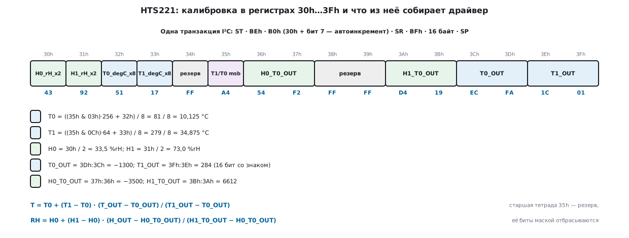
Three subtleties that make drivers report wrong values:
- T0 and T1 are stored multiplied by 8 and take 10 bits: the 8 low bits are in 32h and 33h, the two high bits in bits 1:0 and 3:2 of register 35h. The upper nibble of 35h is reserved; mask it off.
- H0 and H1 are stored multiplied by 2.
- The counts H0_T0_OUT, H1_T0_OUT, T0_OUT, T1_OUT and the outputs themselves are 16-bit signed.
The datasheet gives one example for each line: T0_OUT = 300 at 80/8 = 10 °C, T1_OUT = 500 at 160/8 = 20 °C, a count of 400 gives 15.0 °C; H0_T0_OUT = 4000h at 40/2 = 20 %rH, H1_T0_OUT = 6000h at 80/2 = 40 %rH, a count of 5000h gives 30.0 %rH. Both driver variants give exactly 15.0000 and 30.0000 on these numbers.
39в.5 The driver: bus through pointers, errors, two ways of computing
The driver does not know which chip it runs on: the bus is given to it as three pointers to functions — read, write and delay — as in the ST drivers. On the F4 these are three lines around HAL (the address in HAL is 8-bit, hence the shift):
static int bus_read(void *h, uint8_t addr7, uint8_t sub, uint8_t *d, uint16_t n)
{
    return HAL_I2C_Mem_Read(h, (uint16_t)(addr7 << 1), sub, I2C_MEMADD_SIZE_8BIT, d, n, 10) != HAL_OK;
}
Error codes: HTS_EBUS (−1, no acknowledge on the bus), HTS_EID (−2,
wrong WHO_AM_I), HTS_ETIMEOUT (−3, the measurement did not finish), HTS_ECAL
(−4, calibration with identical points — division by zero is not allowed).
Initialization checks WHO_AM_I, reads the 16 calibration bytes in one
transaction and writes 84h to CTRL_REG1: PD = 1, BDU = 1,
one-shot mode. The measurement:
    for (uint32_t ms = 0;; ms++) {
        if (d->bus.read(d->bus.handle, HTS221_ADDR7, HTS221_STATUS_REG, &st, 1))
            return HTS_EBUS;
        if ((st & ready) == ready)
            break;
        if (ms >= timeout_ms)
            return HTS_ETIMEOUT;
        d->bus.delay_ms(d->bus.handle, 1);
    }
    if (d->bus.read(d->bus.handle, HTS221_ADDR7, HTS221_HUMIDITY_OUT_L | HTS221_AUTOINC, b, 4))
        return HTS_EBUS;
The computation comes in two variants. For the F103 without a floating-point unit
(-DHTS_FIXED) — integers: the result is in hundredths of °C and %rH, the intermediate
product in 64 bits:
int32_t hts_temp_centi(const hts_calib *c, int16_t t_out)
{
    int64_t den = (int64_t)c->t1_out - c->t0_out, num;
    num = ((int64_t)c->t0_x8 * den + ((int64_t)c->t1_x8 - c->t0_x8) * ((int64_t)t_out - c->t0_out)) * 100;
    if (den < 0) { num = -num; den = -den; }
    return div_round(num, 8 * den);
}
For the F407 — the same in float. In both variants humidity is clamped to
0…100 %: the datasheet explicitly requires clamping out-of-range output in software.
armclang builds the driver without warnings: for the F103 (Cortex-M3,
integer variant) — 626 bytes of code, and the only library function needed is the 64-bit
unsigned __aeabi_uldivmod, not a single floating-point function; for the
F407 (Cortex-M4 with FPU, float) — 578 bytes. The bus module on the F4 HAL
builds there as well.
39в.6 Testing without a board
The HTS221 model on the PC is written from the same datasheet: the register map with reset values, auto-increment by bit 7, ONE_SHOT, the STATUS flags, flags cleared by reading the high bytes, BDU, no reply to a foreign address. The model's calibration is set in physical units (T0 = 10.125 °C, T1 = 34.875 °C, H0 = 33.5 %rH, H1 = 73 %rH, counts −1300, 284, −3500, 6612 — 64 LSB per degree and 256 per percent, as in Table 3) and encoded into bytes per Table 19 independently of the parsing in the driver; in the reserved bytes and the upper nibble of 35h the model puts ones to test the masks.
The driver talks to the model through a fake bus. Results:
- 1601 measurements from −40 to 120 °C in steps of 0.1 °C with humidity in steps of
0.13 % — not a single error; the largest deviation from the set value: 0.0063 °C
and 0.0019 %rH in the
floatvariant, 0.01 °C and 0 %rH in the integer one (hundredths). This is the rounding error of the count: half an LSB is 0.0078 °C and 0.0020 %rH. - Each measurement takes three STATUS reads and two 1 ms delays (that is how the model is set up); writes to the calibration and to reserved registers — none.
- A wrong WHO_AM_I (BDh) gives
HTS_EID; no reply givesHTS_EBUS; a measurement that never finishes givesHTS_ETIMEOUTafter 51 STATUS reads and 50 ms; T1_OUT = T0_OUT givesHTS_ECAL; the sensor in power-down (PD = 0) — ONE_SHOT does not work, alsoHTS_ETIMEOUT.
The comparison with other drivers is done by a script. From ST's hts221_reg.h the check
extracts all register addresses, the code BCh, the address BFh and the layout of the bit
fields of CTRL_REG1, CTRL_REG2, STATUS_REG and 35h — everything matches our own
definitions. From the Zephyr driver it extracts the expressions that parse the
calibration and convert the values: on the same 16 bytes they give the same T0, T1, H0,
H1 and counts. But the conversion there is integer, in eighths of a degree and
halves of a percent: on this calibration it falls behind the exact line by up to
0.11 °C and 0.5 %rH — noticeable for a thermometer, irrelevant for a driver
that only needs "dry or damp".
39в.7 Pitfalls
The temperature jumps by 4 °C. Without BDU the low and high bytes can come from different measurements. In the model the output changes from 00FFh to 0100h between the byte reads: without BDU the driver reads 01FFh = 511 LSB, with BDU an honest 00FFh = 255.
All four bytes are the same. Bit 7 in the register address was forgotten: without auto-increment four reads from 28h return the same byte four times (in the model — D4 D4 D4 D4). Calibration read this way turns into garbage: T0 = 835/8 °C.
−40 °C shows as +984 °C. The count was read as unsigned: −4508
turns into 61028. All counts and calibration points are int16_t.
Temperature 8 times too high, humidity 2 times. The division of T0/T1 by 8 and of H0/H1 by 2 was forgotten. And if the two high bits of T0/T1 in 35h are forgotten, 34.875 °C turns into 2.875 °C.
The sensor does not measure. PD = 0 after power-up: until PD = 1 is written, ONE_SHOT starts nothing. Do not use a delay instead of waiting for the flags — the measurement time is not given in the datasheet.
Address 5Fh "does not respond". The bus function expects the 8-bit address BEh, and it was given the 7-bit one, or the other way round.
Writing to Reserved. The datasheet warns of permanent damage; the driver writes only to CTRL_REG1 and CTRL_REG2.
A typo in the datasheet. In Table 19 the least significant bit of register 30h is labelled H0.1 — the same as its neighbour; it is H0.0, and the byte is used as a whole.
39в.8 Summary
- Reading order: the first page (product status), pins and supply, bus and address, register map, control bits, calibration; separately — what the datasheet does not contain (the measurement time).
- HTS221: address BEh/BFh (5Fh), WHO_AM_I = BCh, auto-increment is bit 7 of the register address, CTRL_REG1 = 84h (PD, BDU, one-shot), ONE_SHOT and the flags H_DA/T_DA.
- Calibration: T0/T1 are 10 bits, divide by 8; H0/H1 — divide by 2; counts are 16-bit signed; the datasheet examples are 15.0 °C and 30.0 %rH.
- Driver: bus through pointers, error codes, timeout; F103 — integers,
626 bytes; F407 —
float, 578 bytes. - Without a board: 1601 measurements against the model, error no more than half an LSB (0.0063 °C and 0.0019 %rH); five negative cases; addresses and bits checked against the ST driver, formulas against Zephyr.
Full source code
hts221_drv.c — the HTS221 driver written from the datasheet.
/* hts221_drv.c — раздел 39в: драйвер HTS221 по даташиту DS10866 Rev 5. */
#include "hts221_drv.h"

_Static_assert(HTS221_ADDR7 == (0xBEu >> 1), "BEh/BFh — это 7-битный адрес 5Fh со сдвигом");
_Static_assert((HTS221_CTRL1_PD | HTS221_CTRL1_BDU) == 0x84u, "PD (бит 7) и BDU (бит 2), ODR = 00");
_Static_assert((HTS221_HUMIDITY_OUT_L | HTS221_AUTOINC) == 0xA8u && (HTS221_CALIB_0 | HTS221_AUTOINC) == 0xB0u, "автоинкремент — бит 7");
_Static_assert(0x3Fu - HTS221_CALIB_0 + 1u == 16u, "калибровка — 16 регистров 30h…3Fh");

void hts_decode_calib(hts_calib *c, const uint8_t b[16])      /* b[0] — регистр 30h */
{
    c->h0_x2 = b[0];                                           /* 30h */
    c->h1_x2 = b[1];                                           /* 31h */
    c->t0_x8 = (uint16_t)(b[2] | (b[5] & 0x03u) << 8);         /* 32h и биты 1:0 регистра 35h */
    c->t1_x8 = (uint16_t)(b[3] | (b[5] & 0x0Cu) << 6);         /* 33h и биты 3:2 регистра 35h */
    c->h0_out = (int16_t)(uint16_t)(b[6] | b[7] << 8);         /* 36h, 37h — со знаком */
    c->h1_out = (int16_t)(uint16_t)(b[10] | b[11] << 8);       /* 3Ah, 3Bh */
    c->t0_out = (int16_t)(uint16_t)(b[12] | b[13] << 8);       /* 3Ch, 3Dh */
    c->t1_out = (int16_t)(uint16_t)(b[14] | b[15] << 8);       /* 3Eh, 3Fh */
}

int hts_init(hts221 *d)
{
    uint8_t id = 0, cal[16], v;
    if (d->bus.read(d->bus.handle, HTS221_ADDR7, HTS221_WHO_AM_I, &id, 1))
        return HTS_EBUS;
    if (id != HTS221_ID)
        return HTS_EID;
    if (d->bus.read(d->bus.handle, HTS221_ADDR7, HTS221_CALIB_0 | HTS221_AUTOINC, cal, 16))
        return HTS_EBUS;
    hts_decode_calib(&d->cal, cal);
    if (d->cal.t1_out == d->cal.t0_out || d->cal.h1_out == d->cal.h0_out)
        return HTS_ECAL;
    v = HTS221_CTRL1_PD | HTS221_CTRL1_BDU;                    /* ODR = 00: однократный режим */
    if (d->bus.write(d->bus.handle, HTS221_ADDR7, HTS221_CTRL_REG1, &v, 1))
        return HTS_EBUS;
    return HTS_OK;
}

int hts_measure_raw(hts221 *d, int16_t *h_out, int16_t *t_out, uint32_t timeout_ms)
{
    const uint8_t ready = HTS221_STATUS_H_DA | HTS221_STATUS_T_DA;
    uint8_t v = HTS221_CTRL2_ONE_SHOT, st = 0, b[4];
    if (d->bus.write(d->bus.handle, HTS221_ADDR7, HTS221_CTRL_REG2, &v, 1))
        return HTS_EBUS;
    for (uint32_t ms = 0;; ms++) {
        if (d->bus.read(d->bus.handle, HTS221_ADDR7, HTS221_STATUS_REG, &st, 1))
            return HTS_EBUS;
        if ((st & ready) == ready)
            break;
        if (ms >= timeout_ms)
            return HTS_ETIMEOUT;
        d->bus.delay_ms(d->bus.handle, 1);
    }
    if (d->bus.read(d->bus.handle, HTS221_ADDR7, HTS221_HUMIDITY_OUT_L | HTS221_AUTOINC, b, 4))
        return HTS_EBUS;
    *h_out = (int16_t)(uint16_t)(b[0] | b[1] << 8);
    *t_out = (int16_t)(uint16_t)(b[2] | b[3] << 8);
    return HTS_OK;
}

#ifdef HTS_FIXED
/* n / d с округлением к ближайшему, d > 0 */
static int32_t div_round(int64_t n, int64_t d)
{
    return (int32_t)(n >= 0 ? (n + d / 2) / d : -((-n + d / 2) / d));
}

/* T = (T0·8 + (T1·8 − T0·8)·(T_OUT − T0_OUT)/(T1_OUT − T0_OUT)) / 8, в сотых °C */
int32_t hts_temp_centi(const hts_calib *c, int16_t t_out)
{
    int64_t den = (int64_t)c->t1_out - c->t0_out, num;
    num = ((int64_t)c->t0_x8 * den + ((int64_t)c->t1_x8 - c->t0_x8) * ((int64_t)t_out - c->t0_out)) * 100;
    if (den < 0) { num = -num; den = -den; }
    return div_round(num, 8 * den);
}

/* RH = (H0·2 + (H1·2 − H0·2)·(H_OUT − H0_OUT)/(H1_OUT − H0_OUT)) / 2, в сотых %, обрезка 0…100 % */
int32_t hts_hum_centi(const hts_calib *c, int16_t h_out)
{
    int64_t den = (int64_t)c->h1_out - c->h0_out, num;
    int32_t rh;
    num = ((int64_t)c->h0_x2 * den + ((int64_t)c->h1_x2 - c->h0_x2) * ((int64_t)h_out - c->h0_out)) * 100;
    if (den < 0) { num = -num; den = -den; }
    rh = div_round(num, 2 * den);
    return rh < 0 ? 0 : rh > 10000 ? 10000 : rh;
}
#else
float hts_temp_c(const hts_calib *c, int16_t t_out)
{
    float k = (float)(t_out - c->t0_out) / (float)(c->t1_out - c->t0_out);
    return ((float)c->t0_x8 + ((float)c->t1_x8 - (float)c->t0_x8) * k) / 8.0f;
}

float hts_hum_rh(const hts_calib *c, int16_t h_out)
{
    float k = (float)(h_out - c->h0_out) / (float)(c->h1_out - c->h0_out);
    float rh = ((float)c->h0_x2 + ((float)c->h1_x2 - (float)c->h0_x2) * k) / 2.0f;
    return rh < 0.0f ? 0.0f : rh > 100.0f ? 100.0f : rh;
}
#endif
Next: section 40 "English–Russian correspondences by topic".