 Embedded HandbookApps
99е. BNO055 orientation sensor over I2C: fusion done inside the chip — operating modes, quaternion and Euler angles, calibration and saving it, clock stretching
In 99б the microcontroller assembled the orientation itself: gyroscope, accelerometer and magnetometer, the Madgwick filter, an ellipsoid fit for the field. 99г had a separate magnetometer, 99д the MPU-6050 gyroscope-accelerometer. The BNO055 is all three sensors plus a processor with fusion in one package: it computes the quaternion, Euler angles, gravity and linear acceleration, calibrates its sensors and hands the result over I2C. This section is about talking to it: find it on the bus and reset it, pick an operating mode and wait for the switch, set units and axes, read the quaternion rather than the angles, calibrate and not lose the calibration at every power-up, and survive clock stretching. And the main question — what the microcontroller gains by handing fusion to the chip compared with running the 99б filter itself.
Sources: RM0008 (DocID13902 Rev 17): a slave may hold SCL, and the F1
master waits for it by stopping the high-level counter, p. 758;
receiving three or more bytes as master, method 2, p. 763; one and two
bytes — p. 764; standard mode, CCR and TRISE, pp. 783–784.
DocID13587 Rev 17 (STM32F103x8/xB): Run mode current at 72 MHz with
peripheral clocks off — at most 32.8 mA, table 13, p. 42; in Sleep
mode — at most 7.5 mA, table 15, p. 44. The project has no manufacturer
documentation for the BNO055. Address 0x28, the codes A0 FB 32 0F,
OPR_MODE (0x3D) and mode codes 0x00…0x0C, PWR_MODE (0x3E),
SYS_TRIGGER (0x3F) and the reset command 0x20, AXIS_MAP_CONFIG
(0x41) and the eight axis placements, data addresses and LSB values
follow an open-source driver: OpenMV (commit 6236993,
scripts/libraries/bno055.py, MIT). Everything else — address 0x29,
PAGE_ID, CALIB_STAT, ST_RESULT, SYS_STATUS, SYS_ERR,
UNIT_SEL, AXIS_MAP_SIGN, the 22 offset bytes, mode switch and boot
times, UART frames, the PS0 and PS1 pins — follows the manufacturer's
documentation, not verified: the model repeats it rather than checks
it. The BNO055 fusion algorithm is closed; the model uses its own
filter instead, so the accuracy numbers below describe the model, not
the chip. All numbers come from running the driver
_verify/ori99g/bno99g.c, built by arm-none-eabi-gcc 12.2.1 for the
Cortex-M3 and run in QEMU 7.2 (the mps2-an385 machine), with our own
BNO055 model in Python 3.11; the filter from 99б runs on the same
Cortex-M3 there. The firmware is built by armclang 6.24.
What it is called in the documentation
Original Meaning sensor fusion one orientation from three instruments OPR_MODE, operation modewhich sensors run and whether fusion is computed NDOF,NDOF_FMC_OFFnine degrees of freedom; the same without fast field calibration IMU,COMPASS,M4Gno magnetometer; no gyroscope; the field instead of the gyroscope CONFIGmodeconfiguration mode: units, axes and offsets are written only in it PAGE_IDregister page number UNIT_SELunit selection: m/s² or mg, °/s or rad/s, degrees or radians EUL,QUAEuler angles and the quaternion at the fusion output LIA,GRVlinear acceleration and the gravity vector CALIB_STATcalibration state: two bits for the system and for each sensor offset registers, radius offset registers and calibration sphere radii AXIS_MAP_CONFIG,AXIS_MAP_SIGNaxis permutation and signs for the board mounting ST_RESULTthe power-on self-test result SYS_STATUS,SYS_ERRwhat the system is doing and its error code PS0,PS1interface select pins: I2C or UART
99е.1 Address, codes, reset and register pages
| Module pin | STM32F103 | Purpose |
|---|---|---|
| VIN or 3V3 | 3.3 V | supply |
| GND | GND | ground |
| SCL | PB6 | I2C1 clock |
| SDA | PB7 | I2C1 data |
| COM3 (ADR) | GND or 3.3 V | address 0x28 or 0x29 |
| PS0, PS1 | GND | I2C interface |
The address is 0x28 (so in OpenMV, address=0x28), with COM3 high —
0x29 (per the documentation). Four codes lie in a row from register
0x00: the die A0, accelerometer FB, magnetometer 32, gyroscope 0F;
OpenMV checks all four. The driver tries both addresses and checks the
first code:
/* кто на шине: 0x28 (COM3 = 0) или 0x29 (COM3 = 1); четыре кода — кристалл A0, акселерометр FB, магнитометр 32, гироскоп 0F */
int bno_probe(bno_t *d)
{
    static const uint8_t addr[2] = {BNO_ADDR_A, BNO_ADDR_B};
    for (int i = 0; i < 4; i++)
        d->id[i] = 0;
    for (int i = 0; i < (d->uart ? 1 : 2); i++) {
        d->addr = addr[i];
        if (!d->uart && xfer_done(d, bno_port_xfer(d->addr, 0, 0, 0, 0)) != BNO_OK)
            continue;                                           /* нет ответа на этот адрес */
        if (bno_read_regs(d, BNO_CHIP_ID, d->id, 4) != BNO_OK)
            return BNO_E_BUS;
        return d->id[0] == BNO_ID_CHIP ? BNO_OK : BNO_E_ID;
    }
    return BNO_E_NACK;
}
In the model a board with COM3 grounded is identified in 2 transfers,
with COM3 high — in 3. A chip with another code gives BNO_E_ID, −3; an
empty bus — BNO_E_NACK, −1.
Reset. Bit 5 of SYS_TRIGGER (0x3F), value 0x20, resets the whole
system. After it the chip boots and does not answer its address for a
while; OpenMV simply waits 700 ms. Instead of a blind pause the driver
polls CHIP_ID every 10 ms for up to 1 s:
/* сброс: SYS_TRIGGER = 0x20, затем ждать, пока микросхема снова ответит кодом A0 */
int bno_reset(bno_t *d)
{
    uint8_t id;
    int rc = bno_write_reg(d, BNO_SYS_TRIGGER, BNO_TRIG_RST_SYS);
    if (rc != BNO_OK)
        return rc;
    for (uint32_t t = BNO_BOOT_POLL_MS; t <= BNO_BOOT_MS; t += BNO_BOOT_POLL_MS) {
        bno_port_delay_us(BNO_BOOT_POLL_MS * 1000u);
        if (bno_read_regs(d, BNO_CHIP_ID, &id, 1) == BNO_OK && id == BNO_ID_CHIP) {
            d->boot_ms = t;
            d->mode = BNO_MODE_CONFIG;
            return BNO_OK;
        }
    }
    return BNO_E_TIMEOUT;
}
In the model boot takes 650 ms (per the documentation), and the driver
got an answer at the 650th ms. After reset the chip is in CONFIG.
Pages. Addresses 0x00…0x7F are not enough for everything: PAGE_ID
(0x07) switches between page 0 — data, modes, offsets — and page 1 —
settings of the sensors themselves. Everything in this section is on
page 0. Whoever switched to page 1 and did not switch back reads the
wrong register at 0x00: in the model CHIP_ID reads as 00 on page 1
and A0 on page 0. So configuration starts by writing PAGE_ID = 0.
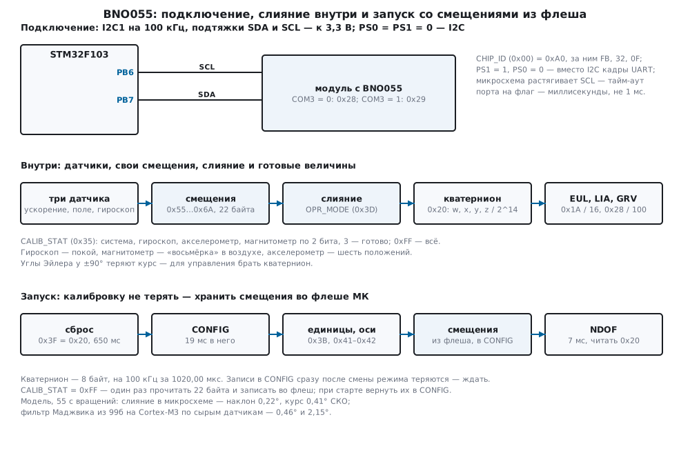
99е.2 Operating modes, switch time, power and self-test
OPR_MODE (0x3D) decides which sensors run and whether fusion is
computed. Codes as in OpenMV:
| Code | Mode | Sensors | Fusion |
|---|---|---|---|
| 0x00 | CONFIG |
— | none; configuration is written only here |
| 0x01…0x07 | ACCONLY … AMG |
one, two or all three | none: raw data |
| 0x08 | IMU (IMUPLUS in OpenMV) |
acceleration, gyroscope | relative orientation, heading without north |
| 0x09 | COMPASS |
acceleration, field | heading from the field, no gyroscope |
| 0x0A | M4G |
acceleration, field | rotation from field changes instead of the gyroscope |
| 0x0B | NDOF_FMC_OFF |
all three | full, without fast field calibration |
| 0x0C | NDOF |
all three | full |
Which sensors run in which mode and what "fast field calibration" means follow the manufacturer's documentation, not verified.
A mode switch is not instant. Per the documentation, going from
CONFIG to an operating mode takes 7 ms, from an operating mode to
CONFIG — 19 ms. While it is in progress, register writes are lost.
The driver waits and reads OPR_MODE back; from one operating mode to
another it goes through CONFIG:
/* режим: из рабочего в рабочий — через CONFIG; после записи — 19 мс в CONFIG или 7 мс из него; затем прочитать обратно */
int bno_set_mode(bno_t *d, uint8_t mode)
{
    uint8_t v;
    int rc;
    if (mode > BNO_MODE_NDOF)
        return BNO_E_ARG;
    if (mode != BNO_MODE_CONFIG && d->mode != BNO_MODE_CONFIG && (rc = bno_set_mode(d, BNO_MODE_CONFIG)) != BNO_OK)
        return rc;
    if ((rc = bno_write_reg(d, BNO_OPR_MODE, mode)) != BNO_OK)
        return rc;
    bno_port_delay_us((mode == BNO_MODE_CONFIG ? BNO_T_TO_CONFIG_MS : BNO_T_FROM_CONFIG_MS) * 1000u);
    if ((rc = bno_read_regs(d, BNO_OPR_MODE, &v, 1)) != BNO_OK)
        return rc;
    d->mode = v & 0x0Fu;
    return d->mode == mode ? BNO_OK : BNO_E_MODE;
}
In the model: CONFIG → NDOF — 7 ms, NDOF → CONFIG — 19 ms,
CONFIG → IMU — 7 ms, IMU → NDOF — 26 ms: writes 3D 00 and
3D 0C. Configuration after reset is the writes 3D 00, 07 00,
3E 00, 3B 00, 41 24 00 and a read of ST_RESULT → 0F, 19 ms
including the wait.
What happens without the pause is visible in the model: from NDOF
write CONFIG and right away UNIT_SEL = 0x04 and AXIS_MAP_CONFIG =
0x21. 50 ms later they read 00 and 24 — both writes are lost. With
bno_set_mode — 04 and 21. And in NDOF itself a UNIT_SEL write is
also lost silently: 00.
Power. PWR_MODE (0x3E): 0 — normal, 1 — low power, 2 — suspend
(codes per the documentation). In the model the data registers freeze in
suspend: the board was turned at 45 °/s, and after a second the
quaternion lags the truth by 42.56°; after returning to normal power —
1.62°.
What the system is doing. SYS_STATUS (0x39): in the model 0 in
CONFIG, 5 — fusion running (NDOF), 6 — running without fusion
(AMG), 4 — self-test in progress, 1 — error; the error code is in
SYS_ERR (0x3A), 3 — "self-test failed" (values per the documentation).
ST_RESULT (0x36) is the power-on self-test result: bits 3…0 —
processor, gyroscope, magnetometer, accelerometer, 0x0F — all good. The
driver checks it in bno_init and can rerun the self-test (bit 0 of
SYS_TRIGGER, only in CONFIG):
/* самотест по команде: только в CONFIG; ждать, пока SYS_STATUS уйдёт из 4 — «идёт самотест» */
int bno_selftest(bno_t *d, uint8_t *st)
{
    uint8_t sys = 4u, err;
    int rc;
    *st = 0;
    if (d->mode != BNO_MODE_CONFIG)
        return BNO_E_MODE;
    if ((rc = bno_write_reg(d, BNO_SYS_TRIGGER, BNO_TRIG_SELFTEST)) != BNO_OK)
        return rc;
    for (uint32_t t = 0; sys == 4u && t < BNO_SELFTEST_MS; t += BNO_BOOT_POLL_MS) {
        bno_port_delay_us(BNO_BOOT_POLL_MS * 1000u);
        if ((rc = bno_status(d, &sys, &err)) != BNO_OK)
            return rc;
    }
    if (sys == 4u)
        return BNO_E_TIMEOUT;
    if ((rc = bno_read_regs(d, BNO_ST_RESULT, st, 1)) != BNO_OK)
        return rc;
    return *st == BNO_ST_ALL ? BNO_OK : BNO_E_SELFTEST;
}
In the model a healthy chip passes the self-test on command in 405 ms,
ST_RESULT = 0x0F. A chip with a broken magnetometer shows 0x0D after
reset — bit 1 is clear — bno_init returns BNO_E_SELFTEST, −6, and
SYS_STATUS and SYS_ERR are 1 and 3.
99е.3 Units, axes, quaternion and Euler angles
Units. UNIT_SEL (0x3B): bit 0 — acceleration in mg instead of
m/s², bit 1 — angular rate in rad/s instead of °/s, bit 2 — angles in
radians, bit 4 — temperature in °F (per the documentation). The driver
always writes it itself rather than trusting the value after reset. LSB
values as in OpenMV:
| Quantity | Registers | Bytes | LSB value |
|---|---|---|---|
| acceleration | 0x08…0x0D | 6 | 1 m/s² = 100 |
| field | 0x0E…0x13 | 6 | 1 µT = 16 |
| angular rate | 0x14…0x19 | 6 | 1 °/s = 16 (rad/s — 900) |
| Euler angles: heading, roll, pitch | 0x1A…0x1F | 6 | 1° = 16 (radian — 900) |
| quaternion w, x, y, z | 0x20…0x27 | 8 | 1 = 2^14 = 16384 |
linear acceleration (LIA) |
0x28…0x2D | 6 | 1 m/s² = 100 |
gravity (GRV) |
0x2E…0x33 | 6 | 1 m/s² = 100 |
All values are 16-bit, least significant byte first. OpenMV divides the angular rate by 900 — that is rad/s, while after reset, per the documentation, it is °/s and 16: such a driver on a stock chip is off by a factor of 56.25. The angles use the same 16 and 900 as the angular rate.
/* кватернион w, x, y, z: 8 байт с 0x20, 1 = 16384 */
int bno_read_quat(bno_t *d, int16_t q[4])
{
    return read_vec(d, BNO_QUA_DATA, q, 4);
}
/* угол Эйлера в сотых градуса из кода в градусном режиме */
int32_t bno_euler_cdeg(int16_t raw)
{
    int32_t a = (int32_t)raw * 100;
    return a >= 0 ? (a + 8) / 16 : -((-a + 8) / 16);
}
In the model the board is still: heading 40.00°, tilts 20.00° and
30.00°. 3 s after starting NDOF with the calibration restored: the
angles are codes 603, 315, 474, that is 37.69°, 19.69° and 29.63°; the
quaternion 14538, 4782, 1226, −5720 — 2.47° from the truth (the model
fusion is still pulling the heading in). Gravity — −330, 457, 803 with
the truth −335.41, 460.76, 798.06, linear acceleration — −8, 10, −3:
almost zero. With bit 2 of UNIT_SEL the heading reads as 639, that is
0.7100 rad.
Gravity and linear acceleration. GRV is where fusion thinks
"down" is, LIA is acceleration minus gravity. They are right as long
as fusion does not mistake acceleration for tilt. In the model the board
is accelerated along x at 2 m/s² for 1 s: before that LIA is −2, 8, 5;
after 0.2 s — 159 (1.59 m/s²), gravity along x — 38; after 0.9 s — 82,
and gravity along x — 121: fusion believed the board had tilted. LIA
catches short jolts, not long acceleration.
Axes. Fusion computes in the chip axes. If the chip sits rotated on
the board, AXIS_MAP_CONFIG (0x41) and AXIS_MAP_SIGN (0x42) permute
the axes: the first has two bits for X, Y, Z — the source axis number,
the second has bits 2, 1, 0 — a minus on X, Y, Z (per the
documentation). OpenMV defines eight placements P0…P7: 0x21 or 0x24 and
signs 04, 00, 06, 02, 03, 01, 07, 05. All eight share one property: a
swap of two axes comes with an odd number of minuses, no swap with an
even number. Otherwise the right-handed axis set becomes left-handed,
and neither the quaternion nor the angles will match the board. The
driver refuses such a write:
/* оси: map — три поля по 2 бита (X — 1:0, Y — 3:2, Z — 5:4: номер исходной оси), sign — биты 2, 1, 0 = минус у X, Y, Z.
 * Правая тройка остаётся правой: перестановка нечётная — минусов нечётное число, чётная — чётное. Только в CONFIG */
int bno_axis_remap(bno_t *d, uint8_t map, uint8_t sign)
{
    uint8_t ax[3], b[2] = {map, sign};
    int odd = 0, minus = 0;
    for (int k = 0; k < 3; k++)
        ax[k] = (uint8_t)(map >> (2 * k) & 3u);
    if (map > 0x3Fu || sign > 7u || ax[0] > 2u || ax[1] > 2u || ax[2] > 2u || ax[0] == ax[1] || ax[0] == ax[2] || ax[1] == ax[2])
        return BNO_E_ARG;
    odd = (ax[0] != 0u) + (ax[1] != 1u) + (ax[2] != 2u) == 2;  /* ровно две оси не на месте — одна перестановка пары */
    for (int k = 0; k < 3; k++)
        minus += sign >> k & 1u;
    if ((minus & 1) != odd)
        return BNO_E_ARG;                                       /* левая тройка: углы и кватернион не сойдутся с осями */
    if (d->mode != BNO_MODE_CONFIG)
        return BNO_E_MODE;
    return bno_write_regs(d, BNO_AXIS_MAP_CONFIG, b, 2);
}
In the model the chip is rotated 90° on the board (chip x along board
y), the board faces north. With the default axes the heading is
270.31°, with P0 (0x21, 0x04) — 0.31°. Swapping X and Y without a sign
(0x21, 0x00) and field value 3 in the map (0x3F) give BNO_E_ARG, −7.
Why the quaternion. One Euler angle has a range of ±90°; as it approaches 90°, heading and the other tilt merge, and the angles themselves lose meaning — the "gimbal lock" of 99б.2. In the model the board is tilted at 30 °/s and the angles and quaternion are read every 50 ms. The largest heading jump between neighbouring reads is 100.25° (angles from 51.75; 89.31; −52.31 to 152.00; 88.81; −152.50 at a true tilt of 87.65°), while the quaternion turned by no more than 1.81° in the same 50 ms. Use the quaternion for control, the angles only for display.
99е.4 Calibration: CALIB_STAT, the procedure and 22 bytes in flash
The BNO055 calibrates itself while fusion runs and reports how far it
got: CALIB_STAT (0x35), two bits each for the system, gyroscope,
accelerometer and magnetometer (bits 7:6, 5:4, 3:2, 1:0), from 0 to 3
(per the documentation).
/* CALIB_STAT: по два бита, 0 — не откалиброван, 3 — полностью */
int bno_calib(bno_t *d, uint8_t *sys, uint8_t *gyr, uint8_t *acc, uint8_t *mag)
{
    uint8_t c = 0;
    int rc = bno_read_regs(d, BNO_CALIB_STAT, &c, 1);
    *sys = c >> 6 & 3u;
    *gyr = c >> 4 & 3u;
    *acc = c >> 2 & 3u;
    *mag = c & 3u;
    return rc;
}
The procedure (per the documentation; the model does the same): the
gyroscope needs a few seconds of rest; the magnetometer — a "figure
eight" in the air so the field passes through all directions; the
accelerometer — six stable positions, a few seconds each, upside down
included. The model has its own rules: 1 s of rest for the gyroscope, a
sphere through the points and 24 of 40 directions around its centre for
the field, 6 positions 30° apart for acceleration. Statuses
system-gyroscope-accelerometer-magnetometer every 3 s: rest 0–3 s,
figure eight 3–18 s, six positions 18–36 s:
| Time | 3 s | 6 s | 9 s | 15 s | 21 s | 27 s | 36 s |
|---|---|---|---|---|---|---|---|
CALIB_STAT |
0300 | 0301 | 0302 | 0303 | 1313 | 2323 | 3333 |
The gyroscope is ready after 1.00 s, the field after 13.00 s, the accelerometer and the whole system after 34.51 s. If the board is only spun on a table around the vertical for 15 s, the field stays at 0 — 0300 after 20 s: the points lie in one plane, and no sphere can be built from them (as in 99г.4).
22 bytes. The calibration result is the registers 0x55 to 0x6A (per
the documentation): accelerometer offsets X, Y, Z (1 m/s² = 100),
magnetometer (1 µT = 16), gyroscope (1 °/s = 16), the accelerometer
radius and the magnetometer radius, all 16-bit least significant byte
first. They are read and written in CONFIG; the driver switches to it
and restores the previous mode:
/* записать сохранённые смещения: только в CONFIG (в рабочем режиме запись не принимается), потом прежний режим */
int bno_offsets_write(bno_t *d, const uint8_t off[BNO_OFFSETS_LEN])
{
    uint8_t prev = d->mode;
    int rc;
    if ((rc = bno_set_mode(d, BNO_MODE_CONFIG)) != BNO_OK || (rc = bno_write_regs(d, BNO_OFFSETS, off, BNO_OFFSETS_LEN)) != BNO_OK)
        return rc;
    return prev == BNO_MODE_CONFIG ? BNO_OK : bno_set_mode(d, prev);
}
In the model the 22 bytes after the procedure are 0E00F6FF1400400110FFE0010800FBFF0600D5032003:
accelerometer 0.14, −0.10, 0.20 m/s² against the true 0.15, −0.10,
0.20; field 20.00, −15.00, 30.00 µT — exactly the model's hard iron;
gyroscope 0.50, −0.31, 0.38 °/s against the true 0.50, −0.30, 0.40;
radii 981 and 800.
Into flash. The calibration lives in the chip until reset or power
loss. As soon as CALIB_STAT = 0xFF the firmware reads the 22 bytes
once and writes them to the last flash page, as in 11.5: a tag, the
bytes, CRC-32 — 8 words:
int bno_rec_unpack(const uint32_t r[BNO_REC_WORDS], uint8_t off[BNO_OFFSETS_LEN])
{
    if (r[0] != BNO_REC_MAGIC)
        return BNO_E_EMPTY;                                     /* стёртая страница: 0xFFFFFFFF */
    if (bno_crc32(r, 4u * (BNO_REC_WORDS - 1u)) != r[BNO_REC_WORDS - 1u])
        return BNO_E_CRC;                                       /* запись побита или недописана */
    for (uint32_t i = 0; i < BNO_OFFSETS_LEN; i++)
        off[i] = (uint8_t)(r[1 + i / 4u] >> (8u * (i % 4u)));
    return BNO_OK;
}
At start-up they go back into the chip, before switching to NDOF:
/* при старте: годная запись во флеше — смещения в микросхему (в CONFIG), иначе калибровать заново */
static void restore_offsets(void)
{
    uint8_t off[BNO_OFFSETS_LEN];
    if (bno_rec_unpack((const uint32_t *)CAL_ADDR, off) == BNO_OK && bno_offsets_write(&dev, off) == BNO_OK)
        restored = 1;
}
In the model the record is 42303535 FFF6000E 01400014 01E0FF10 FFFB0008 03D50006 00000320 D6E446B8; unpacking returns the same
22 bytes, one corrupted bit gives BNO_E_CRC, −8, an erased page —
BNO_E_EMPTY, −9.
What restoring gives — a new power-up of the same board, heading 30°,
NDOF, heading after 0.5…3 s:
| Power-up | Heading error, ° | CALIB_STAT |
|---|---|---|
| no offsets | −40.71 … −40.67 | 0300 |
offsets from flash via bno_offsets_write |
1.08 … 0.87 | 0300 |
the same 22 bytes written in NDOF |
−40.71 … −40.67 | 0300 |
Without offsets the hard iron of 20, −15, 30 µT pulls the heading off by
40° until the board is waved in a figure eight again. Offsets from flash
give one degree at once. Those written in an operating mode are lost.
One more thing: in the model CALIB_STAT stays 0300 after restoring,
although the offsets work — do not wait for 0xFF after restoring (how
the real chip behaves is not verified).
99е.5 Clock stretching, 100 kHz and UART
Per the documentation the BNO055 holds SCL low while it prepares an
answer: a slave may do that, and the F1 I2C master waits by itself — it
checks the line after TRISE and does not count the high level while
it is low (RM0008, p. 758). Trouble comes from masters that cannot do
this, and from the program: the driver waits for each flag SB,
ADDR, RXNE, BTF with a timeout, and if the timeout is shorter
than the chip holds the line, the read is cut off. The documents on disk
do not say how long the BNO055 holds SCL; the model assumes 300 µs on
every read or 1500 µs on every tenth.
| Bus | SCL held | Port timeout | Errors of 100 | Bus per read, µs |
|---|---|---|---|---|
| 100 kHz | 0 µs | 1000 µs | 0 | 1020.00 |
| 100 kHz | 300 µs | 1000 µs | 0 | 1320.00 |
| 100 kHz | 1500 µs, every 10th | 1000 µs | 10 | 1047.00 |
| 100 kHz | 1500 µs, every 10th | 5000 µs | 0 | 1170.00 |
| 400 kHz | 0 µs | 1000 µs | 0 | 255.00 |
| 400 kHz | 300 µs | 1000 µs | 0 | 555.00 |
| 400 kHz | 1500 µs, every 10th | 1000 µs | 10 | 336.75 |
| 400 kHz | 1500 µs, every 10th | 5000 µs | 0 | 405.00 |
The quaternion is 102 SCL clocks: 1020.00 µs at 100 kHz and 255.00 at
400. A port with a 1 ms timeout per flag loses every long read — 10 of
100; with 5 ms — none. The firmware of this section uses 100 kHz: at
100 quaternions a second that is 10.2 % of the bus. CCR = 180 and
TRISE = 37 — 36 MHz / (2 × 180) and 1000 ns × 36 MHz + 1 (RM0008,
pp. 783–784). After a timeout the bus may stay busy — how to free it is
in 17.5 and 17.6.
UART. Pins PS1 = 1, PS0 = 0 switch the BNO055 to UART (per the documentation, 115200 baud). The registers are the same, the exchange is in frames: a request 0xAA, 0x01 (read) or 0x00 (write), register number, length and data; a read answer — 0xBB, length, data; a write answer — 0xEE, 0x01; an error — 0xEE and a code, 0x07 — the internal bus is busy, repeat. There is no stretching here, and the line belongs to the sensor alone. The driver is the same, only the transport changes:
/* 0 — успех; больше нуля — код из ответа 0xEE; BNO_E_UART — ответ не по формату */
int bno_uart_resp(const uint8_t *f, uint32_t nf, int rd, uint8_t *data, uint8_t n)
{
    if (nf >= 2u && f[0] == 0xEEu)
        return (!rd && f[1] == 0x01u) ? BNO_OK : (int)f[1];    /* 0x01 — запись прошла; остальное — ошибка */
    if (!rd || nf != 2u + n || f[0] != 0xBBu || f[1] != n)
        return BNO_E_UART;
    for (uint32_t i = 0; i < n; i++)
        data[i] = f[2 + i];
    return BNO_OK;
}
In the model the same driver over UART identified the codes A0 FB 32 0F,
reset, configured and started NDOF; the quaternion is 14 bytes both
ways, 1215.28 µs. On a 0xEE 0x07 answer the driver repeated the request:
2 transfers, 1 retry, 1736.11 µs. The firmware fw99g.c is I2C only; a
UART port for the F103 is not written.
99е.6 Fusion inside or the 99б filter on the MCU
One stand, one motion model: 55 s — 5 s of rest, 25 s of rotations up
to 60, 30 and 45 °/s, rest, a turn around the vertical at 90 °/s,
swinging. Gyroscope offset 0.50, −0.30, 0.40 °/s, the field and the
accelerometer are calibrated. The first path: the BNO055 in NDOF, the
driver reads the quaternion 100 times a second. The second: the BNO055
in AMG (raw sensors, no fusion), the driver reads 18 bytes and feeds
them to the Madgwick filter of 99б — ahrs99b.c unchanged, β = 1 for
the first 3 s, then 0.033, offset from pauses — on the same Cortex-M3 in
QEMU. Errors after the first 5 s:
| Tilt, RMS | Tilt, max | Heading, RMS | Heading, max | Heading in the 90 °/s turn | Bus per sample, 400 kHz | |
|---|---|---|---|---|---|---|
| fusion in the chip (model) | 0.22° | 0.80° | 0.41° | 8.73° | 0.40° | 255.00 µs |
| Madgwick 99б on the MCU | 0.46° | 1.36° | 2.15° | 6.19° | −1.97° | 480.00 µs |
The accuracy of the first row is the accuracy of the model filter
(Mahony with an integral term, double), not of the real BNO055: its
algorithm is closed, only the structure of the two paths can be
compared. The 99б filter found the offset at 15 pauses in this run.
What is visible even without the closed algorithm:
- Bus. The quaternion is 8 bytes, 255.00 µs at 400 kHz; raw sensors are 18 bytes, 480.00 µs.
- Processor. One
ahrs_updatestep on the Cortex-M3 is 13900 instructions, at 72 MHz no less than 193 µs, at 100 Hz no less than 1.9 % of the processor (99б.6). With the BNO055 inNDOFthese instructions are gone: only parsing 8 bytes. - Microcontroller current. That 1.9 % is Run time instead of Sleep. By the DocID13587 tables (at most 32.8 mA in Run and 7.5 mA in Sleep at 72 MHz) that is about 0.49 mA on average — 1.93 % of the 25.3 mA difference. The current of the BNO055 itself in its modes cannot be checked with the documents on disk: fusion does not disappear, it moves into the chip.
- Latency. BNO055 fusion, per the documentation, updates 100 times a second: register data is up to 10 ms old. A filter on the MCU can run faster if the sensor delivers raw data faster.
- Freedom. Your own filter can be tuned, can drop the magnetometer next to a motor, can be checked. Fusion in the chip is as it is.
99е.7 Pitfalls
No answer at 0x28. COM3 is high — address 0x29; the driver tries both: 3 transfers instead of 2 in the model. Or PS1 is 1 — the chip is on UART.
NACK after reset. The chip is booting: 650 ms in the model. Poll
CHIP_ID instead of sending configuration blindly.
The configuration "does not apply". Writes right after a mode change
are lost: switching to CONFIG takes 19 ms, out of it — 7 ms. In the
model UNIT_SEL and AXIS_MAP_CONFIG written without the pause stayed
00 and 24. Units, axes and offsets are written only in CONFIG — in
NDOF a write is lost silently too.
Calibration is lost at every power-up. Offsets live in the chip
until reset. Without restoring, the model heading is off by 40°, with
the 22 bytes from flash by 1°. Save once when CALIB_STAT = 0xFF,
restore at start-up in CONFIG.
The magnetometer does not calibrate. The board is spun on a table: the points lie in one plane, and in the model the field stays at 0. A figure eight in the air is needed.
A motor nearby — the heading drifted. The motor field adds to the
Earth's. In the model 30, −20, 10 µT were added to a calibrated board
for 4 s: the heading in NDOF moved by 38.64°, 2 s after switching off
still by 26.71°, the field status dropped from 3 to 1. In IMU the same
disturbance gives −0.14°: the magnetometer is not used, but there is no
north either. Keep the sensor away from motors and current-carrying
wires (99г.6), or use IMU and get heading from another source.
Axes mixed up. The chip is rotated on the board: heading 270.31° instead of 0 in the model. Pick the placement from P0…P7 for the mounting; a swap without a sign (a left-handed set) is refused by the driver.
The heading jumps near the vertical. Euler angles near ±90°: a jump of 100.25° in 50 ms while the quaternion turns by 1.81°. Use the quaternion.
The angular rate is 56 times off. It is divided by 900, while
UNIT_SEL by default is °/s and 16 codes.
A read breaks every few seconds. The chip holds SCL longer than the port timeout: 10 errors of 100 at 1 ms and none at 5 ms in the model.
Supply. The chip itself is not for 5 V (per the documentation); modules with a regulator and level shifting are powered from 5 V, the bare chip and a module without a regulator — only from 3.3 V. PB6 and PB7 of the F103 tolerate 5 V (FT, DocID13587, p. 32), but pull-ups to 5 V on the line hit the BNO055.
99е.8 Summary
- Address 0x28 or 0x29 by COM3; codes A0 FB 32 0F from 0x00; after reset
(0x20 into 0x3F) — 650 ms with no answer in the model, poll
CHIP_ID. - Mode —
OPR_MODE(0x3D):CONFIG0x00,IMU0x08,NDOF0x0C; 19 ms intoCONFIG, 7 ms out of it; writes during a switch and configuration outsideCONFIGare lost. - Quaternion — 8 bytes from 0x20, 1 = 16384; angles — 1° = 16;
LIAandGRV— 1 m/s² = 100. Near ±90° Euler angles give a heading jump of 100.25° in 50 ms — use the quaternion. - Axes —
AXIS_MAP_CONFIGandAXIS_MAP_SIGNonly as a right-handed set: P0 brought the heading to 0.31° instead of 270.31°. - Calibration:
CALIB_STAT2 bits each; in the model gyroscope — 1.00 s, figure eight — 13.00 s, six positions — 34.51 s. 22 bytes from 0x55 — into flash at 0xFF, back inCONFIGat start-up: heading 1.08° instead of −40.71°. - Clock stretching: the F1 waits by itself (RM0008, p. 758), but the port timeout must be milliseconds: at 1 ms the model gives 10 breaks of 100, at 5 ms — 0. Or UART (PS1 = 1): 14 bytes of quaternion — 1215.28 µs.
- Fusion inside takes 13900 instructions per step of the 99б filter off the Cortex-M3 (no less than 1.9 % of the processor at 100 Hz) and 10 bus bytes per sample. In the model tilt 0.22° and heading 0.41° RMS against 0.46° and 2.15° for the 99б filter, but the accuracy of real BNO055 fusion cannot be checked with the documents on disk.
Full sources
bno99g.h — registers, modes, units, delays, error codes, the port and the driver functions.
/* bno99g.h — раздел 99е: драйвер BNO055 — опознание, сброс, режимы работы, единицы, оси, кватернион и углы Эйлера,
 * линейное ускорение и тяжесть, статус калибровки, 22 байта смещений и их запись во флеш, самотест, кадры UART.
 * Регистров микроконтроллера не знает: говорит с микросхемой только через порт bno_port_*. В прошивке fw99g.c порт —
 * I2C1 STM32F103, в стенде host99g.c — модель model99g.py.
 * Карта регистров, коды режимов, задержки и формат кадров UART — по документации производителя BNO055 (в проекте её
 * нет, не проверено); адрес 0x28, коды A0 FB 32 0F, OPR_MODE 0x3D и коды 0x00…0x0C, PWR_MODE 0x3E, SYS_TRIGGER 0x3F
 * (0x20 — сброс), AXIS_MAP 0x41/0x42, данные 0x08…0x34 и их цена разряда совпадают с bno055.py из OpenMV. */
#ifndef BNO99G_H
#define BNO99G_H
#include <stdint.h>

/* ── адрес и регистры страницы 0 ──────────────────────────────────────── */
#define BNO_ADDR_A          0x28u       /* вывод COM3 на земле */
#define BNO_ADDR_B          0x29u       /* COM3 на питании */
#define BNO_CHIP_ID         0x00u       /* 4 байта: кристалл, акселерометр, магнитометр, гироскоп */
#define BNO_ID_CHIP         0xA0u
#define BNO_ID_ACC          0xFBu
#define BNO_ID_MAG          0x32u
#define BNO_ID_GYR          0x0Fu
#define BNO_PAGE_ID         0x07u       /* 0 — данные и настройка, 1 — настройка датчиков */
#define BNO_ACC_DATA        0x08u       /* 18 байт: ускорение, поле, угловая скорость; X, Y, Z младшим первым */
#define BNO_EUL_DATA        0x1Au       /* 6 байт: курс, крен, тангаж */
#define BNO_QUA_DATA        0x20u       /* 8 байт: w, x, y, z */
#define BNO_LIA_DATA        0x28u       /* 6 байт линейного ускорения, следом 6 байт тяжести (GRV, 0x2E) */
#define BNO_GRV_DATA        0x2Eu
#define BNO_TEMP            0x34u
#define BNO_CALIB_STAT      0x35u       /* биты 7:6 — система, 5:4 — гироскоп, 3:2 — акселерометр, 1:0 — магнитометр */
#define BNO_ST_RESULT       0x36u       /* 3 — процессор, 2 — гироскоп, 1 — магнитометр, 0 — акселерометр */
#define BNO_SYS_STATUS      0x39u
#define BNO_SYS_ERR         0x3Au
#define BNO_UNIT_SEL        0x3Bu
#define BNO_OPR_MODE        0x3Du
#define BNO_PWR_MODE        0x3Eu
#define BNO_SYS_TRIGGER     0x3Fu
#define BNO_AXIS_MAP_CONFIG 0x41u       /* за ним AXIS_MAP_SIGN (0x42) */
#define BNO_OFFSETS         0x55u       /* 22 байта: смещения акселерометра, магнитометра, гироскопа, два радиуса */
#define BNO_OFFSETS_LEN     22u

/* ── режимы, питание, единицы, команды ───────────────────────────────── */
enum { BNO_MODE_CONFIG = 0x00, BNO_MODE_ACCONLY = 0x01, BNO_MODE_MAGONLY = 0x02, BNO_MODE_GYRONLY = 0x03,
       BNO_MODE_ACCMAG = 0x04, BNO_MODE_ACCGYRO = 0x05, BNO_MODE_MAGGYRO = 0x06, BNO_MODE_AMG = 0x07,
       BNO_MODE_IMU = 0x08, BNO_MODE_COMPASS = 0x09, BNO_MODE_M4G = 0x0A, BNO_MODE_NDOF_FMC_OFF = 0x0B,
       BNO_MODE_NDOF = 0x0C };
enum { BNO_PWR_NORMAL = 0x00, BNO_PWR_LOW = 0x01, BNO_PWR_SUSPEND = 0x02 };
#define BNO_UNIT_MG         0x01u       /* ускорение в мg, иначе м/с² */
#define BNO_UNIT_RPS        0x02u       /* угловая скорость в рад/с, иначе °/с */
#define BNO_UNIT_RAD        0x04u       /* углы Эйлера в радианах, иначе в градусах */
#define BNO_UNIT_FAHR       0x10u       /* температура в °F, иначе в °C */
#define BNO_TRIG_SELFTEST   0x01u
#define BNO_TRIG_RST_SYS    0x20u
#define BNO_ST_ALL          0x0Fu
#define BNO_SYS_FUSION      5u          /* SYS_STATUS: слияние работает */
#define BNO_SYS_ERROR       1u          /* SYS_STATUS: ошибка, подробности в SYS_ERR */

/* ── цена разряда ─────────────────────────────────────────────────────── */
#define BNO_LSB_DEG         16          /* углы Эйлера: 16 кодов на градус */
#define BNO_LSB_RAD         900         /* или 900 на радиан */
#define BNO_LSB_QUAT        16384       /* кватернион: 2^14 на единицу */
#define BNO_LSB_MS2         100         /* ускорение, LIA и GRV: 100 кодов на 1 м/с² */
#define BNO_LSB_DPS         16          /* угловая скорость: 16 кодов на °/с */
#define BNO_LSB_UT          16          /* поле: 16 кодов на мкТл */

/* ── задержки ─────────────────────────────────────────────────────────── */
#define BNO_T_FROM_CONFIG_MS 7u         /* из CONFIG в любой рабочий режим */
#define BNO_T_TO_CONFIG_MS  19u         /* из рабочего режима в CONFIG */
#define BNO_BOOT_MS         1000u       /* после сброса ждать ответа не дольше */
#define BNO_BOOT_POLL_MS    10u
#define BNO_SELFTEST_MS     1000u

enum { BNO_OK = 0, BNO_E_NACK = -1, BNO_E_BUS = -2, BNO_E_ID = -3, BNO_E_TIMEOUT = -4, BNO_E_MODE = -5,
       BNO_E_SELFTEST = -6, BNO_E_ARG = -7, BNO_E_CRC = -8, BNO_E_EMPTY = -9, BNO_E_UART = -10 };

typedef struct {
    uint8_t addr, mode, units, uart;    /* uart = 1: кадры UART вместо I2C */
    uint8_t id[4];
    uint32_t xfers, errors, retries, boot_ms;
} bno_t;

/* ── порт ─────────────────────────────────────────────────────────────── */
/* I2C: ntx байт записи, затем (если nrx) повторный старт и nrx байт чтения; ntx = nrx = 0 — только адрес.
 * 0, BNO_E_NACK или BNO_E_BUS (в том числе — истёк тайм-аут, пока микросхема держала SCL) */
int bno_port_xfer(uint8_t addr7, const uint8_t *tx, uint32_t ntx, uint8_t *rx, uint32_t nrx);
/* UART: отправить ntx байт и принять до max байт ответа; число принятых или BNO_E_BUS */
int bno_port_uart(const uint8_t *tx, uint32_t ntx, uint8_t *rx, uint32_t max);
void bno_port_delay_us(uint32_t us);

/* ── регистры и режимы ────────────────────────────────────────────────── */
int bno_write_regs(bno_t *d, uint8_t reg, const uint8_t *buf, uint32_t n);
int bno_write_reg(bno_t *d, uint8_t reg, uint8_t val);
int bno_read_regs(bno_t *d, uint8_t reg, uint8_t *buf, uint32_t n);
int bno_probe(bno_t *d);
int bno_reset(bno_t *d);
int bno_set_mode(bno_t *d, uint8_t mode);
int bno_set_mode_nowait(bno_t *d, uint8_t mode);
int bno_axis_remap(bno_t *d, uint8_t map, uint8_t sign);
int bno_init(bno_t *d, uint8_t units, uint8_t map, uint8_t sign);
int bno_selftest(bno_t *d, uint8_t *st);
int bno_status(bno_t *d, uint8_t *sys, uint8_t *err);

/* ── данные ───────────────────────────────────────────────────────────── */
int16_t bno_le16(const uint8_t *b);
int bno_read_quat(bno_t *d, int16_t q[4]);
int bno_read_euler(bno_t *d, int16_t e[3]);
int bno_read_lia_grv(bno_t *d, int16_t lia[3], int16_t grv[3]);
int bno_read_amg(bno_t *d, int16_t acc[3], int16_t mag[3], int16_t gyr[3]);
int32_t bno_euler_cdeg(int16_t raw);
int bno_calib(bno_t *d, uint8_t *sys, uint8_t *gyr, uint8_t *acc, uint8_t *mag);

/* ── смещения и флеш ──────────────────────────────────────────────────── */
#define BNO_REC_WORDS       8u          /* метка, 22 байта смещений и 2 байта нулей, CRC-32 — 32 байта */
#define BNO_REC_MAGIC       0x42303535u /* «B055» */
int bno_offsets_read(bno_t *d, uint8_t off[BNO_OFFSETS_LEN]);
int bno_offsets_write(bno_t *d, const uint8_t off[BNO_OFFSETS_LEN]);
uint32_t bno_crc32(const void *p, uint32_t n);
void bno_rec_pack(const uint8_t off[BNO_OFFSETS_LEN], uint32_t r[BNO_REC_WORDS]);
int bno_rec_unpack(const uint32_t r[BNO_REC_WORDS], uint8_t off[BNO_OFFSETS_LEN]);

/* ── кадры UART (PS1 = 1, PS0 = 0) ───────────────────────────────────── */
uint32_t bno_uart_req(uint8_t *f, int rd, uint8_t reg, const uint8_t *data, uint8_t n);
int bno_uart_resp(const uint8_t *f, uint32_t nf, int rd, uint8_t *data, uint8_t n);

#endif
bno99g.c — the driver: identification, reset, modes, axes, self-test, data, calibration, the flash record, UART frames.
/* bno99g.c — раздел 99е: драйвер BNO055. Один и тот же файл собирается в прошивку (armclang, Cortex-M3) и в стенд
* (arm-none-eabi-gcc, Cortex-M3 в QEMU): микроконтроллера он не знает, только порт bno_port_*.
* Всё целыми: кватернион — в 1/16384, углы — в сотых градуса, ускорения — в сотых м/с², как в регистрах. */
#include "bno99g.h"
#define UART_TRIES 3u /* ответ 0xEE 0x07 — «шина занята»: повторить */
static int xfer_done(bno_t *d, int rc)
{
d->xfers++;
if (rc)
d->errors++;
return rc;
}
/* ── кадры UART: запрос 0xAA, чтение/запись, регистр, длина[, данные]; ответ 0xBB, длина, данные или 0xEE, код ── */
uint32_t bno_uart_req(uint8_t *f, int rd, uint8_t reg, const uint8_t *data, uint8_t n)
{
f[0] = 0xAAu;
f[1] = rd ? 0x01u : 0x00u;
f[2] = reg;
f[3] = n;
if (rd)
return 4u;
for (uint32_t i = 0; i < n; i++)
f[4 + i] = data[i];
return 4u + n;
}
/* 0 — успех; больше нуля — код из ответа 0xEE; BNO_E_UART — ответ не по формату */
int bno_uart_resp(const uint8_t *f, uint32_t nf, int rd, uint8_t *data, uint8_t n)
{
if (nf >= 2u && f[0] == 0xEEu)
return (!rd && f[1] == 0x01u) ? BNO_OK : (int)f[1]; /* 0x01 — запись прошла; остальное — ошибка */
if (!rd || nf != 2u + n || f[0] != 0xBBu || f[1] != n)
return BNO_E_UART;
for (uint32_t i = 0; i < n; i++)
data[i] = f[2 + i];
return BNO_OK;
}
static int uart_xfer(bno_t *d, int rd, uint8_t reg, uint8_t *buf, uint32_t n)
{
uint8_t f[4 + BNO_OFFSETS_LEN + 2];
int rc = BNO_E_UART;
if (n > BNO_OFFSETS_LEN)
return BNO_E_ARG;
for (uint32_t t = 0; t < UART_TRIES; t++) {
uint32_t nf = bno_uart_req(f, rd, reg, buf, (uint8_t)n);
int got = xfer_done(d, bno_port_uart(f, nf, f, sizeof f));
if (got < 0)
return got;
rc = bno_uart_resp(f, (uint32_t)got, rd, buf, (uint8_t)n);
if (rc != 0x07) /* 0x07 — переполнение шины внутри: повтор */
break;
d->retries++;
}
return rc > 0 ? BNO_E_UART : rc;
}
int bno_write_regs(bno_t *d, uint8_t reg, const uint8_t *buf, uint32_t n)
{
uint8_t b[1 + BNO_OFFSETS_LEN];
if (n > BNO_OFFSETS_LEN)
return BNO_E_ARG;
if (d->uart) {
for (uint32_t i = 0; i < n; i++)
b[i] = buf[i];
return uart_xfer(d, 0, reg, b, n);
}
b[0] = reg;
for (uint32_t i = 0; i < n; i++)
b[1 + i] = buf[i];
return xfer_done(d, bno_port_xfer(d->addr, b, n + 1u, 0, 0));
}
int bno_write_reg(bno_t *d, uint8_t reg, uint8_t val)
{
return bno_write_regs(d, reg, &val, 1);
}
/* номер регистра, повторный старт, n байт подряд */
int bno_read_regs(bno_t *d, uint8_t reg, uint8_t *buf, uint32_t n)
{
if (d->uart)
return uart_xfer(d, 1, reg, buf, n);
return xfer_done(d, bno_port_xfer(d->addr, ®, 1, buf, n));
}
/* кто на шине: 0x28 (COM3 = 0) или 0x29 (COM3 = 1); четыре кода — кристалл A0, акселерометр FB, магнитометр 32, гироскоп 0F */
int bno_probe(bno_t *d)
{
static const uint8_t addr[2] = {BNO_ADDR_A, BNO_ADDR_B};
for (int i = 0; i < 4; i++)
d->id[i] = 0;
for (int i = 0; i < (d->uart ? 1 : 2); i++) {
d->addr = addr[i];
if (!d->uart && xfer_done(d, bno_port_xfer(d->addr, 0, 0, 0, 0)) != BNO_OK)
continue; /* нет ответа на этот адрес */
if (bno_read_regs(d, BNO_CHIP_ID, d->id, 4) != BNO_OK)
return BNO_E_BUS;
return d->id[0] == BNO_ID_CHIP ? BNO_OK : BNO_E_ID;
}
return BNO_E_NACK;
}
/* сброс: SYS_TRIGGER = 0x20, затем ждать, пока микросхема снова ответит кодом A0 */
int bno_reset(bno_t *d)
{
uint8_t id;
int rc = bno_write_reg(d, BNO_SYS_TRIGGER, BNO_TRIG_RST_SYS);
if (rc != BNO_OK)
return rc;
for (uint32_t t = BNO_BOOT_POLL_MS; t <= BNO_BOOT_MS; t += BNO_BOOT_POLL_MS) {
bno_port_delay_us(BNO_BOOT_POLL_MS * 1000u);
if (bno_read_regs(d, BNO_CHIP_ID, &id, 1) == BNO_OK && id == BNO_ID_CHIP) {
d->boot_ms = t;
d->mode = BNO_MODE_CONFIG;
return BNO_OK;
}
}
return BNO_E_TIMEOUT;
}
/* только запись OPR_MODE — без паузы и проверки; так делать не надо (99е.7) */
int bno_set_mode_nowait(bno_t *d, uint8_t mode)
{
int rc = bno_write_reg(d, BNO_OPR_MODE, mode);
if (rc == BNO_OK)
d->mode = mode;
return rc;
}
/* режим: из рабочего в рабочий — через CONFIG; после записи — 19 мс в CONFIG или 7 мс из него; затем прочитать обратно */
int bno_set_mode(bno_t *d, uint8_t mode)
{
uint8_t v;
int rc;
if (mode > BNO_MODE_NDOF)
return BNO_E_ARG;
if (mode != BNO_MODE_CONFIG && d->mode != BNO_MODE_CONFIG && (rc = bno_set_mode(d, BNO_MODE_CONFIG)) != BNO_OK)
return rc;
if ((rc = bno_write_reg(d, BNO_OPR_MODE, mode)) != BNO_OK)
return rc;
bno_port_delay_us((mode == BNO_MODE_CONFIG ? BNO_T_TO_CONFIG_MS : BNO_T_FROM_CONFIG_MS) * 1000u);
if ((rc = bno_read_regs(d, BNO_OPR_MODE, &v, 1)) != BNO_OK)
return rc;
d->mode = v & 0x0Fu;
return d->mode == mode ? BNO_OK : BNO_E_MODE;
}
/* оси: map — три поля по 2 бита (X — 1:0, Y — 3:2, Z — 5:4: номер исходной оси), sign — биты 2, 1, 0 = минус у X, Y, Z.
* Правая тройка остаётся правой: перестановка нечётная — минусов нечётное число, чётная — чётное. Только в CONFIG */
int bno_axis_remap(bno_t *d, uint8_t map, uint8_t sign)
{
uint8_t ax[3], b[2] = {map, sign};
int odd = 0, minus = 0;
for (int k = 0; k < 3; k++)
ax[k] = (uint8_t)(map >> (2 * k) & 3u);
if (map > 0x3Fu || sign > 7u || ax[0] > 2u || ax[1] > 2u || ax[2] > 2u || ax[0] == ax[1] || ax[0] == ax[2] || ax[1] == ax[2])
return BNO_E_ARG;
odd = (ax[0] != 0u) + (ax[1] != 1u) + (ax[2] != 2u) == 2; /* ровно две оси не на месте — одна перестановка пары */
for (int k = 0; k < 3; k++)
minus += sign >> k & 1u;
if ((minus & 1) != odd)
return BNO_E_ARG; /* левая тройка: углы и кватернион не сойдутся с осями */
if (d->mode != BNO_MODE_CONFIG)
return BNO_E_MODE;
return bno_write_regs(d, BNO_AXIS_MAP_CONFIG, b, 2);
}
/* CONFIG, обычное питание, страница 0, единицы, оси; самотест после включения — все четыре бита */
int bno_init(bno_t *d, uint8_t units, uint8_t map, uint8_t sign)
{
uint8_t st;
int rc;
d->mode = 0xFFu; /* не знаем, в каком режиме микросхема: сначала в CONFIG */
if ((rc = bno_write_reg(d, BNO_OPR_MODE, BNO_MODE_CONFIG)) != BNO_OK)
return rc;
bno_port_delay_us(BNO_T_TO_CONFIG_MS * 1000u);
d->mode = BNO_MODE_CONFIG;
if ((rc = bno_write_reg(d, BNO_PAGE_ID, 0u)) != BNO_OK || (rc = bno_write_reg(d, BNO_PWR_MODE, BNO_PWR_NORMAL)) != BNO_OK
|| (rc = bno_write_reg(d, BNO_UNIT_SEL, units)) != BNO_OK || (rc = bno_axis_remap(d, map, sign)) != BNO_OK)
return rc;
d->units = units;
if ((rc = bno_read_regs(d, BNO_ST_RESULT, &st, 1)) != BNO_OK)
return rc;
return st == BNO_ST_ALL ? BNO_OK : BNO_E_SELFTEST;
}
/* SYS_STATUS и SYS_ERR одним чтением */
int bno_status(bno_t *d, uint8_t *sys, uint8_t *err)
{
uint8_t b[2];
int rc = bno_read_regs(d, BNO_SYS_STATUS, b, 2);
*sys = b[0];
*err = b[1];
return rc;
}
/* самотест по команде: только в CONFIG; ждать, пока SYS_STATUS уйдёт из 4 — «идёт самотест» */
int bno_selftest(bno_t *d, uint8_t *st)
{
uint8_t sys = 4u, err;
int rc;
*st = 0;
if (d->mode != BNO_MODE_CONFIG)
return BNO_E_MODE;
if ((rc = bno_write_reg(d, BNO_SYS_TRIGGER, BNO_TRIG_SELFTEST)) != BNO_OK)
return rc;
for (uint32_t t = 0; sys == 4u && t < BNO_SELFTEST_MS; t += BNO_BOOT_POLL_MS) {
bno_port_delay_us(BNO_BOOT_POLL_MS * 1000u);
if ((rc = bno_status(d, &sys, &err)) != BNO_OK)
return rc;
}
if (sys == 4u)
return BNO_E_TIMEOUT;
if ((rc = bno_read_regs(d, BNO_ST_RESULT, st, 1)) != BNO_OK)
return rc;
return *st == BNO_ST_ALL ? BNO_OK : BNO_E_SELFTEST;
}
int16_t bno_le16(const uint8_t *b)
{
return (int16_t)((uint16_t)b[1] << 8 | b[0]); /* младший байт первым */
}
static int read_vec(bno_t *d, uint8_t reg, int16_t *v, uint32_t n)
{
uint8_t b[18];
int rc = bno_read_regs(d, reg, b, 2u * n);
for (uint32_t i = 0; i < n; i++)
v[i] = rc == BNO_OK ? bno_le16(b + 2 * i) : 0;
return rc;
}
/* кватернион w, x, y, z: 8 байт с 0x20, 1 = 16384 */
int bno_read_quat(bno_t *d, int16_t q[4])
{
return read_vec(d, BNO_QUA_DATA, q, 4);
}
/* курс, крен, тангаж: 6 байт с 0x1A, 16 кодов на градус (или 900 на радиан) */
int bno_read_euler(bno_t *d, int16_t e[3])
{
return read_vec(d, BNO_EUL_DATA, e, 3);
}
/* линейное ускорение и тяжесть одной пачкой: 12 байт с 0x28, 100 кодов на 1 м/с² */
int bno_read_lia_grv(bno_t *d, int16_t lia[3], int16_t grv[3])
{
int16_t v[6];
int rc = read_vec(d, BNO_LIA_DATA, v, 6);
for (int k = 0; k < 3; k++) {
lia[k] = v[k];
grv[k] = v[3 + k];
}
return rc;
}
/* сырые датчики одной пачкой: 18 байт с 0x08 — ускорение, поле, угловая скорость */
int bno_read_amg(bno_t *d, int16_t acc[3], int16_t mag[3], int16_t gyr[3])
{
int16_t v[9];
int rc = read_vec(d, BNO_ACC_DATA, v, 9);
for (int k = 0; k < 3; k++) {
acc[k] = v[k];
mag[k] = v[3 + k];
gyr[k] = v[6 + k];
}
return rc;
}
/* угол Эйлера в сотых градуса из кода в градусном режиме */
int32_t bno_euler_cdeg(int16_t raw)
{
int32_t a = (int32_t)raw * 100;
return a >= 0 ? (a + 8) / 16 : -((-a + 8) / 16);
}
/* CALIB_STAT: по два бита, 0 — не откалиброван, 3 — полностью */
int bno_calib(bno_t *d, uint8_t *sys, uint8_t *gyr, uint8_t *acc, uint8_t *mag)
{
uint8_t c = 0;
int rc = bno_read_regs(d, BNO_CALIB_STAT, &c, 1);
*sys = c >> 6 & 3u;
*gyr = c >> 4 & 3u;
*acc = c >> 2 & 3u;
*mag = c & 3u;
return rc;
}
/* 22 байта смещений: в CONFIG, одной пачкой, потом вернуть прежний режим */
int bno_offsets_read(bno_t *d, uint8_t off[BNO_OFFSETS_LEN])
{
uint8_t prev = d->mode;
int rc;
if ((rc = bno_set_mode(d, BNO_MODE_CONFIG)) != BNO_OK || (rc = bno_read_regs(d, BNO_OFFSETS, off, BNO_OFFSETS_LEN)) != BNO_OK)
return rc;
return prev == BNO_MODE_CONFIG ? BNO_OK : bno_set_mode(d, prev);
}
/* записать сохранённые смещения: только в CONFIG (в рабочем режиме запись не принимается), потом прежний режим */
int bno_offsets_write(bno_t *d, const uint8_t off[BNO_OFFSETS_LEN])
{
uint8_t prev = d->mode;
int rc;
if ((rc = bno_set_mode(d, BNO_MODE_CONFIG)) != BNO_OK || (rc = bno_write_regs(d, BNO_OFFSETS, off, BNO_OFFSETS_LEN)) != BNO_OK)
return rc;
return prev == BNO_MODE_CONFIG ? BNO_OK : bno_set_mode(d, prev);
}
/* ── запись для флеша: метка, 22 байта смещений и два нуля, CRC-32 ── */
uint32_t bno_crc32(const void *p, uint32_t n)
{
const uint8_t *b = p;
uint32_t c = 0xFFFFFFFFu;
while (n--) {
c ^= *b++;
for (int i = 0; i < 8; i++)
c = c & 1u ? c >> 1 ^ 0xEDB88320u : c >> 1;
}
return ~c;
}
void bno_rec_pack(const uint8_t off[BNO_OFFSETS_LEN], uint32_t r[BNO_REC_WORDS])
{
r[0] = BNO_REC_MAGIC;
for (uint32_t i = 1; i < BNO_REC_WORDS - 1u; i++)
r[i] = 0;
for (uint32_t i = 0; i < BNO_OFFSETS_LEN; i++)
r[1 + i / 4u] |= (uint32_t)off[i] << (8u * (i % 4u));
r[BNO_REC_WORDS - 1u] = bno_crc32(r, 4u * (BNO_REC_WORDS - 1u));
}
int bno_rec_unpack(const uint32_t r[BNO_REC_WORDS], uint8_t off[BNO_OFFSETS_LEN])
{
if (r[0] != BNO_REC_MAGIC)
return BNO_E_EMPTY; /* стёртая страница: 0xFFFFFFFF */
if (bno_crc32(r, 4u * (BNO_REC_WORDS - 1u)) != r[BNO_REC_WORDS - 1u])
return BNO_E_CRC; /* запись побита или недописана */
for (uint32_t i = 0; i < BNO_OFFSETS_LEN; i++)
off[i] = (uint8_t)(r[1 + i / 4u] >> (8u * (i % 4u)));
return BNO_OK;
}
fw99g.c — F103 firmware: I2C1 at 100 kHz with a timeout for stretched SCL, offsets from and into flash, the quaternion 100 times a second.
/* fw99g.c — раздел 99е: BNO055 на STM32F103 (BluePill), 72 МГц, APB1 = 36 МГц.
 * I2C1: PB6 — SCL, PB7 — SDA (открытый сток, 100 кГц). Выводы модуля: COM3 на земле (адрес 0x28), PS0 = PS1 = 0 (I2C).
 * Запуск: кто на шине, сброс, CONFIG, единицы (м/с², °/с, градусы, °C), оси по умолчанию; смещения — из последней
 * страницы флеша, если там годная запись; режим NDOF. Дальше SysTick 100 раз в секунду: кватернион (8 байт), раз в
 * секунду — CALIB_STAT; как только он 0xFF и смещения ещё не сохранены — 22 байта в CONFIG, запись во флеш, снова NDOF.
 * Порт терпит растянутый SCL: ожидание каждого флага — до 5 мс.
 * Через отладчик: quat[], calib, saved, restored, bus_errors. Тактирование до 72 МГц — как в разделе 6. */
#include "stm32f10x.h"
#include "bno99g.h"

#define CPU_HZ          72000000u
#define APB1_MHZ        36u
#define I2C_TIMEOUT_US  5000u           /* байт на 100 кГц — 90 мкс; остальное — запас на растянутый SCL */
#define CAL_ADDR        0x0800FC00u     /* последняя страница 1 Кбайт у F103C8 */

static bno_t dev;
static volatile uint32_t ticks;
volatile int16_t quat[4];
volatile uint8_t calib, saved, restored;
volatile uint32_t bus_errors;

void SysTick_Handler(void)
{
    ticks++;
}

static int expired(uint32_t t0, uint32_t us)
{
    return DWT->CYCCNT - t0 >= us * (CPU_HZ / 1000000u);
}

void bno_port_delay_us(uint32_t us)
{
    uint32_t t0 = DWT->CYCCNT;
    while (!expired(t0, us)) {
    }
}

int bno_port_uart(const uint8_t *tx, uint32_t ntx, uint8_t *rx, uint32_t max)
{
    (void)tx;
    (void)ntx;
    (void)rx;
    (void)max;
    return BNO_E_BUS;                                   /* в этой прошивке только I2C */
}

static void gpio_i2c1_init(void)
{
    RCC->APB2ENR |= RCC_APB2ENR_IOPBEN;
    RCC->APB1ENR |= RCC_APB1ENR_I2C1EN;
    /* PB6, PB7 — альтернативная функция, открытый сток, 50 МГц (1111) */
    GPIOB->CRL = (GPIOB->CRL & 0x00FFFFFFu) | 0xFF000000u;
    I2C1->CR1 = 0;                                      /* настраивать при PE = 0 */
    I2C1->CR2 = APB1_MHZ;
    I2C1->CCR = 180u;                                   /* стандартный режим: 36 МГц / (2 × 180) = 100 кГц */
    I2C1->TRISE = APB1_MHZ + 1u;                        /* 1000 нс × 36 МГц = 36 → 36 + 1 = 37 */
    I2C1->CR1 = I2C_CR1_PE;
}

static int sr1_wait(uint16_t mask)
{
    uint32_t t0 = DWT->CYCCNT;
    while (!(I2C1->SR1 & mask)) {
        if (I2C1->SR1 & I2C_SR1_AF)
            return BNO_E_NACK;
        if (expired(t0, I2C_TIMEOUT_US))
            return BNO_E_BUS;                           /* SCL прижат дольше 5 мс или шина встала */
    }
    return BNO_OK;
}

static int fail(int rc)
{
    I2C1->CR1 |= I2C_CR1_STOP;
    I2C1->SR1 = (uint16_t)~I2C_SR1_AF;                  /* AF снимается записью нуля */
    I2C1->CR1 = (uint16_t)((I2C1->CR1 & ~I2C_CR1_POS) | I2C_CR1_ACK);
    if (rc == BNO_E_BUS)
        bus_errors++;
    return rc;
}

/* приём n байт ведущим: один — RM0008, с. 764; два — с. 764, бит POS; три и больше — способ 2, с. 763 */
static int rx_n(uint8_t *rx, uint32_t n)
{
    int rc;
    if (n == 1u) {
        I2C1->CR1 &= (uint16_t)~I2C_CR1_ACK;            /* NACK — до снятия ADDR */
        (void)I2C1->SR2;
        I2C1->CR1 |= I2C_CR1_STOP;
        if ((rc = sr1_wait(I2C_SR1_RXNE)) != BNO_OK)
            return rc;
        rx[0] = (uint8_t)I2C1->DR;
    } else if (n == 2u) {                               /* POS и ACK стоят с повторного старта */
        (void)I2C1->SR2;
        I2C1->CR1 &= (uint16_t)~I2C_CR1_ACK;
        if ((rc = sr1_wait(I2C_SR1_BTF)) != BNO_OK)
            return rc;
        I2C1->CR1 |= I2C_CR1_STOP;
        rx[0] = (uint8_t)I2C1->DR;
        rx[1] = (uint8_t)I2C1->DR;
        I2C1->CR1 &= (uint16_t)~I2C_CR1_POS;
    } else {
        (void)I2C1->SR2;                                /* ADDR снят, ACK = 1 */
        for (uint32_t i = 0; i + 3u < n; i++) {
            if ((rc = sr1_wait(I2C_SR1_RXNE)) != BNO_OK)
                return rc;
            rx[i] = (uint8_t)I2C1->DR;
        }
        if ((rc = sr1_wait(I2C_SR1_BTF)) != BNO_OK)     /* N−2 в DR, N−1 в сдвиговом, SCL прижат */
            return rc;
        I2C1->CR1 &= (uint16_t)~I2C_CR1_ACK;
        rx[n - 3u] = (uint8_t)I2C1->DR;
        if ((rc = sr1_wait(I2C_SR1_BTF)) != BNO_OK)
            return rc;
        I2C1->CR1 |= I2C_CR1_STOP;
        rx[n - 2u] = (uint8_t)I2C1->DR;
        if ((rc = sr1_wait(I2C_SR1_RXNE)) != BNO_OK)
            return rc;
        rx[n - 1u] = (uint8_t)I2C1->DR;
    }
    I2C1->CR1 |= I2C_CR1_ACK;
    return BNO_OK;
}

/* старт, адрес, байты записи; при rd — повторный старт и адрес чтения (ADDR ещё не снят) */
static int addr_phase(uint8_t addr7, const uint8_t *tx, uint32_t ntx, int rd, int pos)
{
    int rc;
    uint32_t t0 = DWT->CYCCNT;
    while (I2C1->SR2 & I2C_SR2_BUSY) {
        if (expired(t0, I2C_TIMEOUT_US))
            return BNO_E_BUS;
    }
    I2C1->CR1 |= I2C_CR1_ACK | I2C_CR1_START;
    if ((rc = sr1_wait(I2C_SR1_SB)) != BNO_OK)
        return rc;
    I2C1->DR = (uint8_t)(addr7 << 1);
    if ((rc = sr1_wait(I2C_SR1_ADDR)) != BNO_OK)
        return rc;
    (void)I2C1->SR2;
    for (uint32_t i = 0; i < ntx; i++) {
        if ((rc = sr1_wait(I2C_SR1_TXE)) != BNO_OK)
            return rc;
        I2C1->DR = tx[i];
    }
    if (ntx && (rc = sr1_wait(I2C_SR1_BTF)) != BNO_OK)
        return rc;
    if (!rd)
        return BNO_OK;
    if (pos)
        I2C1->CR1 |= I2C_CR1_POS;
    I2C1->CR1 |= I2C_CR1_START;
    if ((rc = sr1_wait(I2C_SR1_SB)) != BNO_OK)
        return rc;
    I2C1->DR = (uint8_t)(addr7 << 1 | 1u);
    return sr1_wait(I2C_SR1_ADDR);
}

int bno_port_xfer(uint8_t addr7, const uint8_t *tx, uint32_t ntx, uint8_t *rx, uint32_t nrx)
{
    int rc;
    if (nrx && !ntx)
        return BNO_E_BUS;
    if ((rc = addr_phase(addr7, tx, ntx, nrx != 0u, nrx == 2u)) != BNO_OK)
        return fail(rc);
    if (!nrx) {
        I2C1->CR1 |= I2C_CR1_STOP;
        return BNO_OK;
    }
    if ((rc = rx_n(rx, nrx)) != BNO_OK)
        return fail(rc);
    return BNO_OK;
}

/* ── смещения во флеше: стереть страницу и записать 16 полуслов (раздел 11.5) ── */
static void flash_wait(void)
{
    while (FLASH->SR & FLASH_SR_BSY) {
    }
}

static int rec_save(const uint32_t r[BNO_REC_WORDS])
{
    const uint16_t *h = (const uint16_t *)r;
    int bad = 0;
    FLASH->KEYR = 0x45670123u;
    FLASH->KEYR = 0xCDEF89ABu;
    flash_wait();
    FLASH->CR |= FLASH_CR_PER;
    FLASH->AR = CAL_ADDR;
    FLASH->CR |= FLASH_CR_STRT;
    flash_wait();
    FLASH->CR &= ~FLASH_CR_PER;
    FLASH->CR |= FLASH_CR_PG;
    for (uint32_t i = 0; i < 2u * BNO_REC_WORDS; i++) {
        *(volatile uint16_t *)(CAL_ADDR + 2u * i) = h[i];
        flash_wait();
        bad |= (FLASH->SR & FLASH_SR_PGERR) != 0u;
    }
    FLASH->CR &= ~FLASH_CR_PG;
    FLASH->CR |= FLASH_CR_LOCK;
    return bad ? BNO_E_CRC : BNO_OK;
}

/* при старте: годная запись во флеше — смещения в микросхему (в CONFIG), иначе калибровать заново */
static void restore_offsets(void)
{
    uint8_t off[BNO_OFFSETS_LEN];
    if (bno_rec_unpack((const uint32_t *)CAL_ADDR, off) == BNO_OK && bno_offsets_write(&dev, off) == BNO_OK)
        restored = 1;
}

/* полная калибровка (0xFF) — один раз прочитать 22 байта и сохранить */
static void save_offsets(void)
{
    uint8_t off[BNO_OFFSETS_LEN];
    uint32_t r[BNO_REC_WORDS];
    if (bno_offsets_read(&dev, off) != BNO_OK)
        return;
    bno_rec_pack(off, r);
    if (rec_save(r) == BNO_OK)
        saved = 1;
}

int main(void)
{
    uint32_t last = 0;
    CoreDebug->DEMCR |= CoreDebug_DEMCR_TRCENA_Msk;
    DWT->CYCCNT = 0;
    DWT->CTRL |= DWT_CTRL_CYCCNTENA_Msk;
    gpio_i2c1_init();
    while (bno_probe(&dev) != BNO_OK)
        bno_port_delay_us(100000u);                     /* нет ответа ни на 0x28, ни на 0x29, или код не A0 */
    while (bno_reset(&dev) != BNO_OK || bno_init(&dev, 0u, 0x24u, 0x00u) != BNO_OK)
        bno_port_delay_us(100000u);
    restore_offsets();
    while (bno_set_mode(&dev, BNO_MODE_NDOF) != BNO_OK)
        bno_port_delay_us(100000u);
    SysTick_Config(CPU_HZ / 100u);                      /* 100 раз в секунду — как обновляется слияние */
    for (;;) {
        __WFI();
        if (ticks == last)
            continue;
        last = ticks;
        int16_t q[4];
        if (bno_read_quat(&dev, q) == BNO_OK)
            for (int k = 0; k < 4; k++)
                quat[k] = q[k];
        if (last % 100u == 0u) {
            uint8_t s, g, a, m;
            if (bno_calib(&dev, &s, &g, &a, &m) == BNO_OK) {
                calib = (uint8_t)(s << 6 | g << 4 | a << 2 | m);
                if (calib == 0xFFu && !saved)
                    save_offsets();
            }
        }
    }
}
Next: section 100 "Distance and presence: HC-SR04 and HC-SR501" — ultrasound and timer input capture, a divider on the five-volt echo and an infrared motion sensor.