 Embedded HandbookApps
3а. Bit operations
All microcontroller programming comes down to one action: set, clear or read bits in a register. Section 3 covered the language as a whole; this one is about the part of it that is used in every second line, and about the traps hidden in it. Every formula here is checked by the compiler.
Terms used in the documentation
Term Meaning bit mask a word with ones in the bits of interest to set / clear / toggle a bit to write a one, a zero, or the opposite value into a bit bit field a field of several bits position / mask ( _Pos/_Msk)the position and mask of a field in the headers shift left / right moving the bits of a word towards the high or low end logical / arithmetic shift a shift that brings in zeros / that copies the sign bit integer promotion narrow types are widened to intin expressionsread-modify-write read the value, change it, write it back population count the number of ones in a word leading zeros the zeros above the highest one alignment placing data at addresses that are multiples of its size endianness the byte order of multi-byte numbers
3а.1 Four actions on a bit
Everything starts with a mask — a word in which exactly the required bit is set:
#define BIT(n) (1u << (n)) /* BIT(13) == 0x2000 */
| Action | Expression | Result for x = 0x20, bit 5 |
|---|---|---|
| set | x \| BIT(5) |
0x20 |
| clear | x & ~BIT(5) |
0x00 |
| toggle | x ^ BIT(5) |
0x00 (was set — cleared) |
| test | (x & BIT(5)) != 0 |
true |
Three operations — three operators: | sets, & ~ clears, ^ flips.
The fourth — & — reads, and here is the first trap.
⚠️ The result of
x & BIT(n)is a mask, not 0/1. For bit 5 it is0x20or0. The comparison(x & BIT(5)) == 1is always false except for bit zero — and the code "works" right up to the moment the bit is moved. Compare with zero:!= 0. The same applies toREAD_BITfrom the headers (appendix B).
The suffix u in 1u is not decoration; more on it in 3а.3.
3а.2 A field of several bits
The pin mode in GPIOC->CRH takes two bits, the prescaler in RCC->CFGR
four. For a field of width w at position p there are three formulas:
#define FIELD_MSK(p, w)        (((1u << (w)) - 1u) << (p))
#define FIELD_GET(x, p, w)     (((x) >> (p)) & ((1u << (w)) - 1u))
#define FIELD_SET(x, p, w, v)  (((x) & ~FIELD_MSK(p, w)) | (((v) << (p)) & FIELD_MSK(p, w)))
For three bits from position 4: the mask is 0x70; from 0x65 you extract 6;
writing 2 gives 0x25.
The CMSIS headers spare you the arithmetic — each field has ready-made
names: GPIO_CRH_MODE13 is the mask 0x00300000, GPIO_CRH_MODE13_0
its low bit. The F4 also has _Pos: GPIO_MODER_MODER13_Pos equals 26.
Writing a field with them:
GPIOC->CRH = (GPIOC->CRH & ~GPIO_CRH_MODE13) | GPIO_CRH_MODE13_1; /* режим 2: выход 2 МГц */
Or with the same macro from the header: MODIFY_REG(GPIOC->CRH, GPIO_CRH_MODE13, GPIO_CRH_MODE13_1).
In the debugger's register window this line looks like this — starting from the value after reset:
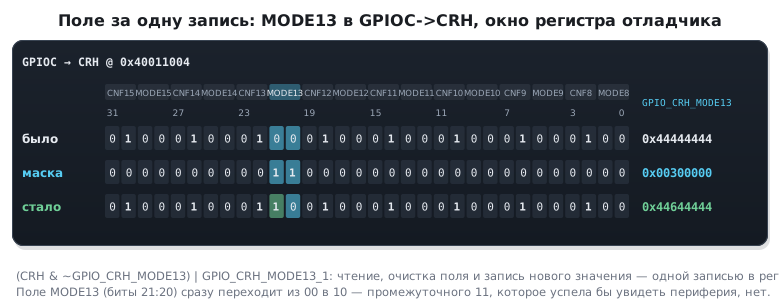
⚠️ The pin field on F1 is four bits,
MODEandCNF. The line above changes onlyMODE13, whileCNF13stays01, as after reset: "after" in the figure is0x44644444, the pin nibble is0110, an open-drain output. This does not bother the LED on PC13, which lights on a zero, but an ordinary push-pull output is obtained only if both fields are cleared (section 8.4):
c
GPIOC->CRH = (GPIOC->CRH & ~(GPIO_CRH_MODE13 | GPIO_CRH_CNF13)) | GPIO_CRH_MODE13_1;   /* output 2 MHz, push-pull: CNF13 = 00 */
Then "after" is
0x44244444.⚠️ A field is changed with one expression, not two. Writing
0b10where0b01was, in two steps — "set the high bit, clear the low one" — means getting0b11for an instant: a foreign value that the peripheral has time to see. For a pin mode this is a short pulse in the wrong direction, for a clock prescaler a frequency jump.MODIFY_REGclears the field and writes the new one in a single operation on the register.
3а.3 Shifts: sign and width
Three things about << and >>, each of which has cost someone a day.
A literal without a suffix is a signed int. 1 << 31 overflows int
and by the standard is undefined behaviour. The compiler is entitled to do
anything, and with optimisation it does. 1u << 31 is unsigned,
defined, equal to 0x80000000. The rule: masks only with u.
A right shift of a negative signed value is defined by the compiler. GCC and
armclang for ARM make it arithmetic: the sign is replicated, -16 >> 2 equals -4, not 0x3FFFFFFC. For a register
where the top bit is a flag rather than a sign, this is garbage. The rule: shift
only unsigned values.
A shift by the type width or more is undefined. x << 32 for a
32-bit x on Cortex‑M gives zero, but the compiler is entitled to reason
otherwise and, for example, throw out a check. A variable shift amount
must be less than the width.
A right shift of an unsigned value is logical, zeros come in from the left:
0x80000000u >> 31 equals 1.
3а.4 The promotion trap: ~ on narrow types
Before any arithmetic uint8_t and uint16_t are turned into int.
Usually this goes unnoticed. With inversion it does not:
uint8_t x = 0x0F;
if (~x == 0xF0) { /* НИКОГДА не истинно */ }
~x is computed over an int: ~0x0000000F = 0xFFFFFFF0, not 0xF0.
Assigning back into a uint8_t would truncate it to 0xF0 — but a comparison before
the assignment compares with 0xFFFFFFF0. The cure is a mask or a cast:
(~x & 0xFFu) or (uint8_t)~x.
The same promotion makes uint8_t a = 200, b = 100; a + b equal to 300,
not 44 — which is usually what you want; but in the comparison a + b > 255 it gives
not what those who remember about byte overflow expect.
3а.5 One-line techniques
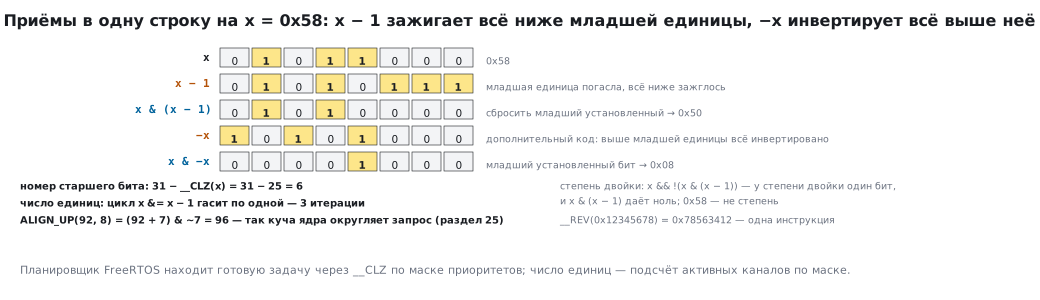
Formulas that look like tricks until you see them laid out bit by bit:
| Task | Expression | Why it works |
|---|---|---|
| power of two | x && !(x & (x - 1)) |
a power of two has one bit; x − 1 clears it and sets everything below |
| lowest set bit | x & -x |
two's complement: −x inverts everything above the lowest one |
| clear the lowest set bit | x & (x - 1) |
the same subtraction, without & with the original |
align up to a (a power of two) |
(x + a - 1) & ~(a - 1) |
top up to the boundary, zero the tail |
| number of the highest bit | 31 - __CLZ(x) |
one instruction counts the leading zeros |
| number of ones | the loop x &= x - 1 |
each iteration clears one; there are as many iterations as ones |
| byte swap | __REV(x) |
one instruction; 0x12345678 → 0x78563412 |
| parity | the low bit of the number of ones |
Alignment is exactly what the kernel heap does (section 25): a request for 92 bytes
gives ALIGN_UP(92, 8) = 96. The number of ones comes in handy for counting
active channels in a mask; the highest bit for priorities: the FreeRTOS
scheduler finds the ready task via __CLZ.
3а.6 Registers: read-modify-write and how to avoid it
GPIOC->ODR |= BIT(13) is three instructions: read, modify, write
(section 30). An interrupt between the first and the third that changed another bit in the same
register is lost: the write puts back the old value of that bit.
The STM32 has two ways of managing with a single write.
BSRR: set and reset without reading anything. The lower 16 bits say
what to set, the upper ones what to reset; zeros touch nothing:
GPIOC->BSRR = GPIO_BSRR_BS13 | GPIO_BSRR_BR5; /* 0x00202000: 13 в 1, 5 в 0, остальное как было */
This is atomic, two instructions faster and does not depend on what
happens in interrupts. For pins — always BSRR, ODR only
for reading the state of the outputs.
Bit-banding: each bit has its own address. On Cortex‑M3/M4 bit 13
of the ODR register of port C corresponds to the word 0x422201B4 in the alias
region; a write there is atomic and does not touch the neighbours (section 1,
appendix B). It works for the first megabyte of peripherals and the first megabyte
of SRAM — where a block has no BSRR of its own — except for flag registers
that are cleared by writing: the bus itself reads the whole register (section 1.5).
Only the addresses 0x4000 0000–0x400F FFFF have aliases: on F4 these
cover APB1, APB2 and AHB1, while the blocks on AHB2 (USB OTG FS from 0x5000 0000,
DCMI, RNG), the FSMC registers and the core registers do not have them.
⚠️ Bit-banding spoils flag registers. The bus performs a write to the alias as a read of the whole word, a replacement of one bit and a write of the word back. In
EXTI->PR, where a flag is cleared by writing a one, the ones of neighbouring flags that are written back clear them too; inTIMx->SR, where flags are cleared with a zero, a flag raised between the read and the write is lost. Flags are cleared by a direct write of the mask:EXTI->PR = EXTI_PR_PR0,TIM2->SR = ~TIM_SR_UIF.
The third way — exclusive access __LDREXW/__STREXW — is for
variables in memory, not registers (appendix B).
3а.7 C bit fields: not for registers
The language allows a register to be described by a structure with fields of a given width:
typedef struct {
    uint32_t mode : 2;
    uint32_t cnf  : 2;
    uint32_t      : 28;
} pin_cfg_t;
It reads nicely — and is unsuitable for peripheral registers. The standard
does not define in which bits mode lies — the low or the high ones,
with what width the compiler will access memory and whether it will do so in a single
operation. For ARM the order is fixed by the binary interface standard (the first field
is in the low bits), but that does not save registers. Every assignment to a field is
a separate read-modify-write of the whole register: two lines give two
writes and an intermediate value, and flags that are cleared by writing
a one get erased. The access width depends on the compiler options:
optimisation may read a byte instead of a word, and for registers these are
different accesses with different meanings.
For packing your own flags into a structure bit fields are appropriate: the order does not matter, the memory is your own. For registers — only masks and shifts: they mean exactly what is written.
3а.8 Byte order
Cortex‑M stores multi-byte numbers least significant byte first:
0x12345678 lies in memory as 78 56 34 12. This shows up in three places:
when parsing packets from a network, where the opposite order is used (section 37);
when reading sensors that send the most significant byte first (section 17);
when viewing memory in the debugger, where a number "looks reversed".
The cure is __REV for a word and __REV16 for a halfword, or assembling
the number from bytes by hand: (hi << 8) | lo. The second is portable, the first is
one instruction.
3а.9 Pitfalls
A bit test "works" as long as the bit is bit zero. x & BIT(n) gives a mask, not 1; compare with
zero, not with one (3а.1).
A peripheral gets a foreign field value for an instant. A field is changed in one write (MODIFY_REG), not in two steps
"set, then clear" (3а.2).
3а.10 Summary
- A mask is
1u << n;|sets,& ~clears,^flips,&reads — and the result of reading is a mask, not 0/1. - A field is changed with one expression: clear the mask, write the value; two steps give a foreign intermediate value.
- Masks only with
u:1 << 31is undefined behaviour; shift only unsigned values; the shift amount is less than the type width. ~over auint8_tgives anintwith ones in the upper bits; mask or cast.x & (x − 1)clears the lowest one — hence the power-of-two test and counting ones;(x + a − 1) & ~(a − 1)aligns.- For pins —
BSRR, notODR |=: one write instead of three instructions and no race. - C bit fields are for your own structures, not for registers.
- Cortex‑M is least significant byte first;
__REVreverses in one cycle.
Next: section 4 "Toolchain" — where to compile, flash and debug all this.