 Embedded HandbookApps
198р. Mini-project: an OBD-II scanner on STM32 — RPM, speed, temperature and trouble codes
Section 19 took bxCAN apart from the inside, and in 198е it became a sniffer — a device that only listens to the bus. Here, for the first time, the device talks to other people's units: a pocket scanner plugs into the car's diagnostic connector, asks the engine control unit for RPM, speed, coolant temperature and voltage, reads the trouble codes and the vehicle identification number (VIN) and shows it all on a small display. One button pages through the screens, and a long press clears the codes — with a confirmation and a guard against clearing while driving.
Everything that can be checked without a car has been checked. The scanner core (obd_core.c) was built with gcc on a PC and run
against a model of two units on an in-memory bus: a 72 s drive with a start,
acceleration, cruising and a stop, two codes in the engine unit, three in the gearbox, a VIN,
scripted button presses and a lost link. The same test was built with
arm-none-eabi-gcc for Cortex-M3 and run in QEMU — the output matched line for
line. A Python model, with its own code, recomputed the bit timing, the filter,
the frame parsing and the bus load. The BluePill firmware was built with
-Werror; it has not been run on a board or in a car.
References: RM0008 (the bxCAN chapter: bit timing, fig. 233, the CAN_BTR fields,
filters in mask mode, fig. 229, frame length, fig. 234) from the Keil pack
STM32F1xx_DFP 2.4.1. The SAE J1979, J1962 and ISO 15765 standards are paid and were not checked here:
the PID formulas and code decoding were checked against python-obd (decoders.py,
UnitsAndScaling.py); the unit addresses, the functional address 0x7DF, splitting
a response into frames and the VIN — against elm327-emulator (obd_message.py, elm.py);
the ISO-TP defaults — against isotp-c and iso14229; the SSD1306 commands — against
the OLED.cpp driver from IronOS. Licenses: python-obd — GPL-2.0,
elm327-emulator — CC BY-NC-SA 4.0, isotp-c and iso14229 — MIT, IronOS —
GPL-3.0; none of their code is copied into the handbook, only numbers and formats were checked.
bxCAN — section 19, the transceiver and terminators — 19.2, supply input protection —
173, the sniffer — 198е.
Terms used in the documentation
Term Meaning OBD-II, SAE J1979 service (mode) on-board diagnostics; request service (mode): 01 — current data, 03 — codes, 04 — clear, 09 — vehicle information PID (parameter ID) the parameter number inside service 01 DTC (diagnostic trouble code) a fault code, for example P0133 MIL (malfunction indicator lamp) the "check engine" lamp freeze frame a snapshot of parameters at the moment the code appeared functional / physical addressing a request to all units (0x7DF) / to one unit (0x7E0…0x7E7) ISO-TP (ISO 15765-2): single frame, first frame, consecutive frame, flow control transport on top of CAN: single frame, first frame, consecutive frame, flow control block size, STmin how many frames to send without a new FC; the gap between frames P2 timeout how long to wait for the unit's response J1962 connector the 16-pin diagnostic connector load dump a surge when the alternator is disconnected under load
198р.1 What the device does and what it is made of
The scanner is powered from the car's connector, finds the units that answer OBD-II on its own, picks the engine unit and polls it in a loop. There are four screens: live data, trouble codes, VIN and a service screen (which units answered, which PIDs they support, counters). The fifth is the question before clearing the codes.
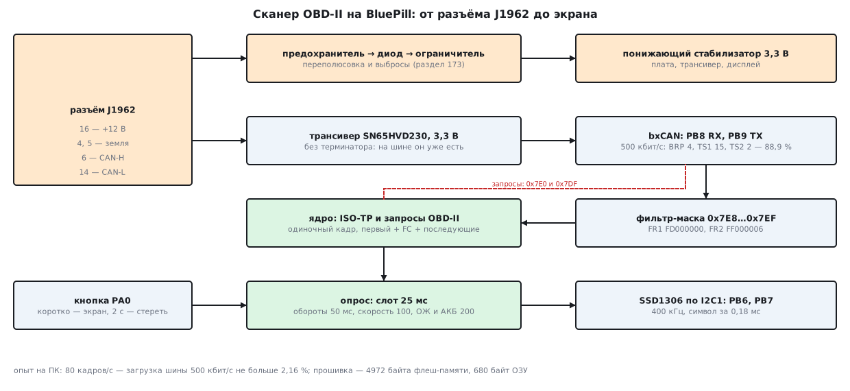
The parts list is approximate; prices are not given:
| What | Which | Why |
|---|---|---|
| board | BluePill, STM32F103C8 | bxCAN, I2C1, 64 KB of Flash |
| transceiver | a module on SN65HVD230 | 3.3 V supply, same as the microcontroller (19.2) |
| connector | an OBD-II (J1962) plug with a cable | pins 4, 5, 6, 14, 16 |
| protection | fuse, diode, unidirectional suppressor | reverse polarity and surges (173) |
| supply | a 12 → 3.3 V buck module | a linear regulator gets hot here (198р.2) |
| display | a 0.96″ SSD1306 module, 128 × 64, I2C | 8 lines of 21 characters |
| button | tactile, to ground | the pull-up is internal |
BluePill pins: CAN_RX and CAN_TX — PB8 and PB9 after remapping
(CAN_REMAP = 10, as in 198е), I2C1 — PB6 and PB7, the button — PA0. Clock —
an 8 MHz crystal × 9 = 72 MHz, APB1 — 36 MHz: bxCAN and I2C1 are clocked from it.
198р.2 Connector, supply and transceiver
The J1962 connector. CAN diagnostics needs five pins: 16 — battery plus, 4 — chassis ground, 5 — signal ground, 6 — CAN-H, 14 — CAN-L. This is the commonly known pinout; it has not been checked against the J1962 standard.
Transceiver. The SN65HVD230 was chosen: it runs from 3.3 V, like the microcontroller (the table in 19.2), and a single 3.3 V rail is enough for the whole board. The TJA1050 runs from 5 V — a second supply rail would be needed, and its RXD output would drive a microcontroller input with a five-volt level (19.2: "a level shifter or tolerant pins"). There is no 120 Ω terminator in the scanner: the car's bus already has two, at the ends of the line (19.2), and the scanner is a stub.
Supply and protection. The order is as in 173.4: fuse, reverse polarity protection (a diode or a transistor), a unidirectional suppressor after it, a bulk capacitor, then the regulator. The suppressor for a car is chosen as described in 173.3: its working voltage is above 24 V, so that it does not conduct during a jump start from an external 24 V battery. A load dump is a surge lasting fractions of a second with energy orders of magnitude larger than the suppressor on a board can absorb (173.3); the circuit in the alternator protects against it, and we only keep it from burning the regulator. There are no load dump numbers here: they were not checked against the standard, this is unverified.
The regulator is a switching one. A linear one would drop 14.4 − 3.3 = 11.1 V and at a current of 50 mA (an example: the scanner's current was not measured) would dissipate 0.555 W.
198р.3 bxCAN: 500 kbit/s and a filter for responses
Bit rate. According to RM0008 (fig. 233), a bit is one synchronization quantum plus TS1 + 1 and TS2 + 1 quanta, and a quantum is (BRP + 1) APB1 clocks. The fields are narrow: TS1 — 4 bits (1…16 quanta), TS2 — 3 bits (1…8), BRP — 10 bits. From 36 MHz, exactly 500 kbit/s comes from 38 combinations, 6 of them with a sample point from 80 to 90 %:
| Prescaler | Quanta per bit | TS1 + TS2 | Sample point |
|---|---|---|---|
| 4 | 18 | 15 + 2 | 88.9 % |
| 4 | 18 | 14 + 3 | 83.3 % |
| 6 | 12 | 9 + 2 | 83.3 % |
| 8 | 9 | 7 + 1 | 88.9 % |
| 9 | 8 | 6 + 1 | 87.5 % |
| 12 | 6 | 4 + 1 | 83.3 % |
The first one is taken: it has the most quanta (a quantum of 111.1 ns), and the
SJW resynchronization jump can be set to 2 quanta — a car has many units with their own crystals.
The sniffer in 198е used 9 × 8 quanta (87.5 %) — that works too. Which sample
point a particular car requires cannot be checked without ISO 15765-4.
In the register this is 0x011E0003:
CAN1->BTR = ((CAN_SJW - 1u) << 24) | ((CAN_TS2 - 1u) << 20) | ((CAN_TS1 - 1u) << 16) | (CAN_BRP - 1u);
Filter. The units respond on identifiers 0x7E8…0x7EF — eight adjacent ones that differ in the three low bits. So one 32-bit filter in mask mode is enough (RM0008, fig. 229: STID — in bits 31…21, IDE — bit 2, RTR — bit 1). The mask covers the upper 8 bits of the identifier plus IDE and RTR: 29-bit frames and remote frames will not pass.
#define OBD_FR1 ((uint32_t)OBD_RESP_ID << 21)
#define OBD_FR2 (((uint32_t)OBD_RESP_MASK << 21) | 0x4u | 0x2u)   /* IDE = 0 и RTR = 0 — тоже «должно совпасть» */
The result is FR1 = 0xFD000000, FR2 = 0xFF000006. The test ran all 2048 standard identifiers through the same filter: exactly 8 passed, from 0x7E8 to 0x7EF; of the remote frames and 29-bit frames — none. The rest of the car's traffic never reaches the interrupt at all.
198р.4 OBD-II requests on top of ISO-TP
A request is one frame: a length byte (the single frame PCI, 0x0N), the service, the PID number. The frame is always full, 8 bytes; the rest is padded with 0xAA — isotp-c pads with this byte, while elm327-emulator pads with zeros. A functional request goes to 0x7DF (all units hear it), a physical one — to 0x7E0…0x7E7, the response address minus 8 (that is how the addresses are laid out in elm327-emulator: engine 0x7E0/0x7E8, gearbox 0x7E1/0x7E9).
A response longer than 7 bytes is sent as a multi-frame message. The first frame carries 12 bits of length and 6 bytes; the scanner replies with a flow control (FC) frame to the physical address of that unit, and the unit sends the consecutive frames of 7 bytes with sequence numbers 1, 2…:
    } else if (type == 1u) {                    /* первый кадр: длина 12 бит, 6 байт данных */
        obd_frame fc;
        tp.len = (uint16_t)(((f->d[0] & 15u) << 8) | f->d[1]);
        if (tp.len < 8u || tp.len > OBD_BUF || f->dlc < 8u) {
            obd.isotp_err++;
            return;
        }
        for (unsigned i = 0; i < 6u; i++)
            tp.buf[i] = f->d[2u + i];
        tp.got = 6;
        tp.sn = 1;
        tp.from = from;
        tp.active = 1;
        fc.id = from - 8u;                      /* управление потоком — на физический адрес этого ЭБУ */
        fc.dlc = 8;
        fc.d[0] = 0x30;                         /* FC: продолжай */
        fc.d[1] = 0;                            /* размер блока 0 — всё без остановок */
        fc.d[2] = 0;                            /* STmin 0 мс */
The start of the test — the first 207 ms on the bus, verbatim from the run (time in ms, identifier, 8 bytes):
bus t=  1 7DF  02 01 00 AA AA AA AA AA
bus t=  3 7E8  06 41 00 88 18 00 01 AA
bus t=  5 7E9  06 41 00 00 08 00 00 AA
bus t=101 7E0  02 01 20 AA AA AA AA AA
bus t=103 7E8  06 41 20 00 00 00 01 AA
bus t=126 7E0  02 01 40 AA AA AA AA AA
bus t=128 7E8  06 41 40 40 00 00 00 AA
bus t=151 7E0  02 01 01 AA AA AA AA AA
bus t=153 7E8  06 41 01 82 07 65 00 AA
bus t=176 7E0  02 09 02 AA AA AA AA AA
bus t=178 7E8  10 14 49 02 01 57 50 30
bus t=179 7E0  30 00 00 AA AA AA AA AA
bus t=180 7E8  21 5A 5A 5A 39 39 5A 54
bus t=181 7E8  22 53 33 39 30 30 30 30
bus t=201 7DF  01 03 AA AA AA AA AA AA
bus t=203 7E8  06 43 02 01 33 04 20 AA
bus t=205 7E9  10 08 43 03 07 00 07 15
bus t=206 7E1  30 00 00 AA AA AA AA AA
bus t=207 7E9  21 C1 00 AA AA AA AA AA
What happens here:
- 0100 to 0x7DF — "which PIDs 01…20 do you support". Two units answered: 0x7E8 — PIDs 01, 05, 0C, 0D and 20, 0x7E9 — only 0D. The engine unit is the one that knows RPM (0C): 0x7E8. From then on the scanner asks only it, at 0x7E0: on 0x7DF the gearbox would also send the speed (0D) — an extra response to every such request.
- 0120 and 0140 — the next ranges. The last bit of the 0100 response (PID 20) says that 0120 has an answer, and its last bit (PID 40) says that 0140 exists. PID 0x42 (voltage) is in the range 41…60: the 0100 table alone would not be enough.
- 0101 — byte A = 0x82: the top bit means the MIL lamp is on, the lower seven are two codes (decoded as in python-obd).
- 0902 — VIN: the response of 20 bytes (
49 02 01and 17 characters) does not fit into a frame. The first frame10 14— length 0x014, FC to 0x7E0 after 1 ms, then frames 21 and 22. The result isWP0ZZZ99ZTS390000— the number from the example in elm327-emulator. - 03 to 0x7DF — codes. The engine has two (a single frame,
43 02 01 33
   04 20
), the gearbox has three — that is 8 bytes, a multi-frame response, and the FC now goes to 0x7E1.
The formulas are the same as in python-obd (the UAS table: 0x07 — 0.25 rpm per unit, 0x09 — 1 km/h, 0x0B — 0.001 V):
| PID | What | Bytes | Formula |
|---|---|---|---|
| 0C | RPM | A, B | (256·A + B) / 4 rpm |
| 0D | speed | A | A km/h |
| 05 | coolant | A | A − 40 °C |
| 42 | control module voltage | A, B | (256·A + B) / 1000 V |
A trouble code is two bytes. The two top bits are the system letter (P, C, B, U), the next two are the first digit 0…3, the remaining 12 bits are three hexadecimal digits:
    out[0] = sys[code >> 14];
    out[1] = (char)('0' + ((code >> 12) & 3u));                 /* следующие два бита: 0…3 */
    out[2] = hex[(code >> 8) & 15u];
    out[3] = hex[(code >> 4) & 15u];
    out[4] = hex[code & 15u];
The test checked seven codes: 0x0133 — P0133, 0x0420 — P0420, 0x4123 — C0123 (the example from a python-obd comment), 0x8001 — B0001, 0xC100 — U0100, 0x1234 — P1234, 0x3FFF — P3FFF; the Python model decoded them the same way.
198р.5 Polling in a loop, screens and the button
The core is called once per millisecond. There is always one request in flight; a new
one goes out at the start of a 25 ms slot if the previous one has finished. A physical request
ends with the first response or with a 150 ms timeout (this is how long the iso14229 client
waits for a response by default, UDS_CLIENT_DEFAULT_P2_MS). A functional one waits
100 ms and collects the responses of all units. Three timeouts in a row — the message
NO LINK.
The polling order is a table of eight slots; PIDs the unit does not support are skipped:
static const uint8_t POLL[8] = {0x0C, 0x0D, 0x0C, 0x05, 0x0C, 0x0D, 0x0C, 0x42}; /* обороты — каждый второй слот */
RPM changes fastest and goes every 50 ms (20 times per second), speed — every 100 ms, temperature and voltage — every 200 ms. That is exactly what came out in the test: in the 12…48 s stretch, the 010C requests are exactly 50 ms apart (720 requests), 010D — 100 ms, 0105 and 0142 — 200 ms each.
Bus load. 40 requests and 40 responses per second — 80 frames. A frame with 8 bytes is 111 bits including the gap (RM0008, fig. 234), and with worst-case bit stuffing — 135. That is 1.78…2.16 % of a 500 kbit/s bus. The scanner barely disturbs the car; you could ask more often, but the engine unit does not answer instantly, and its response time cannot be measured without a car.
Screens. A line is 21 characters of a 5 × 7 font (6 dots with the gap, 126 of 128), and there are eight lines — one SSD1306 page per line. Screens from the test, verbatim:
screen t=20000 accelerating
|OBD-II  ECU 7E8      |
|RPM       1894 RPM   |
|SPEED       44 KM/H  |
|COOLANT     48 C     |
|BATTERY  14.20 V     |
|MIL ON   DTC  2      |
|                     |
|                     |
screen t=5500 dtc
|STORED DTC:  5       |
|P0133  P0420         |
|P0700  P0715         |
|U0100                |
|                     |
|                     |
|HOLD 2S: CLEAR       |
|PRESS: NEXT          |
The labels are in Latin letters: the firmware font covers only the characters from space to Z — 59 glyphs of 5 bytes each. On the acceleration snapshot the RPM lags the drive's "ground truth" by 46 ms — less than its polling period.
The display must not slow down polling. The whole screen is 1024 bytes over I2C at
400 kHz (9 bits per byte) — 23.1 ms of waiting in the main loop. So each
call sends one character: the address, the 0x40 byte and 6 column bytes — 0.18 ms,
plus three position commands once per line. The screen is fully refreshed in
168 ms, and polling does not shift. The init commands — prefix 0x00 for
commands and 0x40 for data, address 0x3C, charge pump 8D 14, multiplex A8
(height minus 1), COM layout DA (0x02 or 0x12 depending on the
panel) — were checked against OLED.cpp from IronOS; they were not checked against the SSD1306 datasheet.
The button and clearing codes. A short press pages through the screens. A long one (2 s, counted while held, not on release) on the codes screen opens a question:
screen t=28200 confirm
|CLEAR ALL DTC?       |
|ALSO FREEZE FRAME    |
|AND READINESS DATA   |
|IGNITION ON,         |
|ENGINE OFF ONLY      |
|                     |
|HOLD 2S: YES         |
|PRESS: NO           5|
Another long press within 5 s means "yes", a short one means "no", and
5 s of silence also means "no". Service 04 clears more than the codes: in python-obd it is
named "Clear DTCs and Freeze data", and the 0101 response is "Status since DTCs
cleared", so the readiness of the self-test monitors is counted from the
clearing and is reset too. And the cause of the fault does not go anywhere.
That is why the scanner does not clear with the engine running (the last RPM
above zero) or without a link — it shows ENGINE ON: NOT CLEAR.
198р.6 Testing on a PC: a 72-second drive
The bus model: a frame arrives in 1 ms, the engine unit answers after 2 ms, the gearbox — after 4 ms; the response arrives 3 ms after the request. The scenario:
| Time | What happens | What the scanner showed |
|---|---|---|
| 0…2 s | ignition on, engine stopped | found 2 units, VIN, 5 codes |
| 2…10 s | start, idle at 800 rpm | 4 s: 800 rpm, 21 °C, 14.20 V |
| 10…30 s | acceleration to 3000 rpm and 90 km/h, warm-up | 20 s: 1894 rpm, 44 km/h, 48 °C |
| 26…31.5 s | two long presses while driving | 31.02 s: refused ENGINE ON: NOT CLEAR |
| 30…40 s | cruising at 2200 rpm, 90 km/h | 38 s: 2200, 90, 78 °C |
| 52 s | engine switched off | — |
| 54…56.5 s | question — and no answer | 61.02 s: question closed after 5 s |
| 62…67.5 s | question, "yes" | 67.03 s: both units answered 44; 0 codes, MIL off |
| 69…71 s | units silent | 69.45 s: NO LINK; 71.10 s: link restored |
Every decoded value was compared with what the unit model encoded at that
moment: RPM — 1388 responses, speed — 694, temperature — 347,
voltage — 346, zero mismatches. NO LINK appeared after 450 ms
of silence — three timeouts of 150 ms. There are no ISO-TP errors and no extra responses.
The same test was built with arm-none-eabi-gcc 12.2.1 for Cortex-M3 and run in
qemu-system-arm -M netduinoplus2 — the output matched the PC line for line.
The Python model separately recomputed the timing, the filter and the codes, assembled
the VIN and the gearbox responses from frames and compared the values on the screen snapshots with
the drive's "ground truth".
The BluePill firmware (obd_f103.c: clock, bxCAN, I2C1, button, SysTick;
the core is the same) was built with arm-none-eabi-gcc -Os -Wall -Wextra -Werror:
4972 bytes of Flash and 680 bytes of RAM. bxCAN, I2C and the display have not been run on
hardware — QEMU does not model CAN.
How to repeat it in a car: start with the INFO screen — it shows who answered 0100 and which PIDs the engine unit supports. If nobody answered, check pins 6 and 14 and the bit rate: some cars use 29-bit addresses (0x18DB33F1 is their functional address in elm327-emulator), and they need a different filter and addresses.
198р.7 Full firmware code
The firmware is six files of our own: the hardware-free core obd_core.h and
obd_core.c, the F103 register code obd_f103.c, the startup
start_f103.c, the font font5x7.h and the linker script f103.ld. All of them
are given below in full. The pieces from 198р.3…198р.5 are repeated here inside their
functions. There is no third-party code.
The build uses the same commands as the check. CMSIS_F1 is the Device/Include directory
of the Keil STM32F1xx_DFP 2.4.1 pack (it contains stm32f10x.h), CMSIS_CORE is
CMSIS/Core/Include from CMSIS 5.9.0 (github.com/ARM-software/CMSIS_5):
for f in start_f103 obd_f103 obd_core; do
  arm-none-eabi-gcc -mcpu=cortex-m3 -mthumb -Os -Wall -Wextra -Werror -std=c11 -ffreestanding \
    -ffunction-sections -fdata-sections -DSTM32F10X_MD -I. -I$CMSIS_F1 -I$CMSIS_CORE -c $f.c -o $f.o
done
arm-none-eabi-gcc -mcpu=cortex-m3 -mthumb start_f103.o obd_f103.o obd_core.o \
  -T f103.ld -nostdlib -Wl,--gc-sections -o fw.elf -lgcc
Core header. Addresses and filter, all timeouts, the frame and the device state:
/* Раздел 198р «Мини-проект: OBD-II сканер» — ядро без железа.
 * Запросы OBD-II поверх ISO-TP (одиночный кадр туда, одиночный или составной обратно),
 * расписание опроса, разбор PID и кодов ошибок, кнопка и экраны 21 × 8 символов.
 * Одно и то же ядро собирается gcc на ПК (против модели ЭБУ) и arm-none-eabi-gcc для F103. */
#ifndef OBD_CORE_H
#define OBD_CORE_H
#include <stdint.h>

#define OBD_FUNC_ID   0x7DFu    /* функциональный адрес: «все ЭБУ, кто поддерживает OBD» */
#define OBD_RESP_ID   0x7E8u    /* ответы 0x7E8…0x7EF, запрос к одному ЭБУ — ответ минус 8 */
#define OBD_RESP_MASK 0x7F8u    /* 8 младших идентификаторов — в одном фильтре-маске */

/* фильтр bxCAN, 32 бита, режим маски (RM0008, рис. 229): STID в битах 31:21, IDE — бит 2, RTR — бит 1 */
#define OBD_FR1 ((uint32_t)OBD_RESP_ID << 21)
#define OBD_FR2 (((uint32_t)OBD_RESP_MASK << 21) | 0x4u | 0x2u)   /* IDE = 0 и RTR = 0 — тоже «должно совпасть» */

#define OBD_PAD       0xAAu     /* добивка кадра до 8 байт — как ISO_TP_FRAME_PADDING_VALUE в isotp-c */
#define OBD_SLOT_MS   25u       /* один запрос в слот */
#define OBD_P2_MS     150u      /* ждём ответ — как UDS_CLIENT_DEFAULT_P2_MS в iso14229 */
#define OBD_COLLECT_MS 100u     /* функциональный запрос: собираем ответы всех ЭБУ */
#define OBD_LOST_N    3u        /* столько таймаутов подряд — «NO LINK» */
#define OBD_DEBOUNCE_MS 20u
#define OBD_LONG_MS   2000u     /* долгое нажатие */
#define OBD_CONFIRM_MS 5000u    /* окно подтверждения стирания */
#define OBD_BUF       64u       /* буфер сборки ISO-TP */
#define OBD_MAX_DTC   8u
#define OBD_MAX_ECU   8u

typedef struct {
    uint32_t id;
    uint8_t dlc;
    uint8_t d[8];
} obd_frame;

enum { SCR_LIVE, SCR_DTC, SCR_VIN, SCR_INFO, SCR_CONFIRM, SCR_N };

typedef struct {
    /* что знаем о машине */
    uint32_t pids[3];           /* поддержка PID 01…20, 21…40, 41…60 (ответы 0100, 0120, 0140) */
    uint16_t ecu_id[OBD_MAX_ECU];
    uint8_t n_ecu;
    uint16_t engine;            /* ЭБУ двигателя: ответил 0100 и поддерживает 0C */
    /* последние значения; have_* — пришёл ли хоть один ответ */
    uint16_t rpm_raw;           /* 256·A + B, обороты ×4 */
    uint8_t speed, coolant_raw, have;
    uint16_t volt_mv;
    uint8_t mil, n_dtc_mil;     /* из 0101: лампа и число кодов */
    uint16_t dtc[OBD_MAX_DTC];
    uint8_t n_dtc, dtc_read;
    char vin[18];
    /* счётчики */
    uint32_t tx, rx, timeouts, nrc, extra, isotp_err, cleared;
    uint8_t lost, screen, cleared_ok, refused;
} obd_state;

#define HAVE_RPM 1u
#define HAVE_SPEED 2u
#define HAVE_COOL 4u
#define HAVE_VOLT 8u

extern obd_state obd;

void obd_init(void);
void obd_rx(const obd_frame *f, uint32_t now);  /* кадр, прошедший фильтр */
void obd_poll(uint32_t now, int btn_down);      /* вызывать каждую миллисекунду */
int plat_can_send(const obd_frame *f);          /* даёт платформа; 0 — кадр ушёл в ящик */

/* разбор — отдельно, чтобы сверить с моделью */
unsigned obd_dtc_str(uint16_t code, char out[6]);
int32_t obd_decode(uint8_t pid, const uint8_t *ab);    /* 0C — об/мин ×4, 0D — км/ч, 05 — °C, 42 — мВ */
extern char obd_lines[8][22];                   /* экран: 8 строк по 21 символу */
void obd_render(uint32_t now);

/* журнал для опыта на ПК: что ушло и что разобрано; на плате — пустые функции */
void obd_log_req(uint32_t now, uint16_t id, uint8_t svc, uint8_t pid);
void obd_log_val(uint32_t now, uint8_t pid, int32_t v);
#endif
Core: state. One request in flight (job), reassembly of a multi-frame
response (tp), the polling table and the button state:
/* Раздел 198р «Мини-проект: OBD-II сканер» — ядро: ISO-TP, запросы, разбор, кнопка, экраны. */
#include "obd_core.h"

obd_state obd;
char obd_lines[8][22];

static struct {
    uint8_t busy, func, svc, pid, answered;
    uint16_t to;
    uint32_t t0;
} job;                                          /* один запрос в полёте */

static struct {
    uint8_t active, sn;
    uint16_t from, len, got;
    uint8_t buf[OBD_BUF];
} tp;                                           /* сборка составного ответа ISO-TP */

static uint32_t next_slot;
static uint8_t step, poll_i, want_clear, reread, miss;
static const uint8_t POLL[8] = {0x0C, 0x0D, 0x0C, 0x05, 0x0C, 0x0D, 0x0C, 0x42};   /* обороты — каждый второй слот */

static struct {
    uint8_t raw, stable, long_fired;
    uint32_t t_change, t_press, t_confirm;
} btn;

void obd_init(void)
{
    uint8_t *p = (uint8_t *)&obd;
    for (unsigned i = 0; i < sizeof obd; i++)
        p[i] = 0;
    job.busy = 0;
    tp.active = 0;
    next_slot = 0;
    step = poll_i = want_clear = reread = miss = 0;
    btn.raw = btn.stable = btn.long_fired = 0;
    btn.t_change = btn.t_press = btn.t_confirm = 0;
}
Core: request. Whether a PID is supported — from the 0100/0120/0140 maps; the request frame is always 8 bytes with padding; a physical request goes to the engine address minus 8:
static int supported(uint8_t pid)
{
    if (pid == 0u || pid > 0x60u)
        return pid == 0u;
    return (obd.pids[(pid - 1u) / 32u] >> (31u - (pid - 1u) % 32u)) & 1u;
}

static void send(uint16_t id, uint8_t n, uint8_t b0, uint8_t b1, uint8_t b2)
{
    obd_frame f;
    f.id = id;
    f.dlc = 8;                                  /* кадр всегда полный: 8 байт с добивкой */
    f.d[0] = n;                                 /* PCI одиночного кадра: 0x0N, N — байт полезных данных */
    f.d[1] = b0;
    f.d[2] = b1;
    f.d[3] = b2;
    for (unsigned i = 1u + n; i < 8u; i++)
        f.d[i] = OBD_PAD;
    if (plat_can_send(&f) == 0)
        obd.tx++;
}

static void request(uint32_t now, int func, uint8_t svc, uint8_t pid, int has_pid)
{
    job.busy = 1;
    job.func = (uint8_t)func;
    job.svc = svc;
    job.pid = pid;
    job.answered = 0;
    job.to = func ? (uint16_t)OBD_FUNC_ID : (uint16_t)(obd.engine - 8u);
    job.t0 = now;
    if (svc == 0x03u)
        obd.n_dtc = 0;
    send(job.to, has_pid ? 2u : 1u, svc, pid, 0);
    obd_log_req(now, job.to, svc, has_pid ? pid : 0xFFu);
}
Core: formulas and codes. Values are stored as integers: RPM ×4, voltage in millivolts:
int32_t obd_decode(uint8_t pid, const uint8_t *ab)
{
    switch (pid) {
    case 0x0C: return (int32_t)((ab[0] << 8) | ab[1]);          /* (256A + B) / 4 об/мин — храним ×4 */
    case 0x0D: return ab[0];                                    /* A км/ч */
    case 0x05: return (int32_t)ab[0] - 40;                      /* A − 40 °C */
    case 0x42: return (int32_t)((ab[0] << 8) | ab[1]);          /* (256A + B) / 1000 В — храним в мВ */
    default: return 0;
    }
}

unsigned obd_dtc_str(uint16_t code, char out[6])
{
    static const char sys[4] = {'P', 'C', 'B', 'U'};           /* два старших бита: система */
    static const char hex[16] = "0123456789ABCDEF";
    out[0] = sys[code >> 14];
    out[1] = (char)('0' + ((code >> 12) & 3u));                 /* следующие два бита: 0…3 */
    out[2] = hex[(code >> 8) & 15u];
    out[3] = hex[(code >> 4) & 15u];
    out[4] = hex[code & 15u];
    out[5] = 0;
    return 5;
}

static void finish(void)
{
    job.busy = 0;
    miss = 0;
    obd.lost = 0;
}
Core: parsing a message. A 7F rejection, the support maps (the engine ECU is
the one that knows PID 0C), the lamp and the number of codes, values, the code list,
clearing and the VIN:
/* целое сообщение от ЭБУ from: p[0] — ответ службы (запрос + 0x40) */
static void message(uint16_t from, const uint8_t *p, unsigned n, uint32_t now)
{
    obd.rx++;
    if (!job.busy) {
        obd.extra++;
        return;
    }
    if (p[0] == 0x7Fu && n >= 2u && p[1] == job.svc) {     /* отрицательный ответ: 7F, служба, причина */
        obd.nrc++;
        if (!job.func)
            finish();
        return;
    }
    if (p[0] != (uint8_t)(job.svc + 0x40u) || (!job.func && from != obd.engine)) {
        obd.extra++;
        return;
    }
    job.answered = 1;
    if (job.svc == 0x01u) {
        if (n < 2u || p[1] != job.pid) {
            obd.extra++;
            return;
        }
        if ((job.pid == 0x00u || job.pid == 0x20u || job.pid == 0x40u) && n >= 6u) {
            uint32_t bm = ((uint32_t)p[2] << 24) | ((uint32_t)p[3] << 16) | ((uint32_t)p[4] << 8) | p[5];
            if (job.pid == 0x00u && obd.n_ecu < OBD_MAX_ECU)
                obd.ecu_id[obd.n_ecu++] = from;
            if (job.pid == 0x00u && obd.engine == 0u && (bm >> (31u - (0x0Cu - 1u))) & 1u)
                obd.engine = from;              /* ЭБУ двигателя — тот, кто знает обороты */
            if (job.pid != 0x00u || from == obd.engine)
                obd.pids[job.pid / 32u] = bm;
        } else if (job.pid == 0x01u) {
            obd.mil = p[2] >> 7;                /* A7 — лампа MIL, A6…A0 — число кодов */
            obd.n_dtc_mil = p[2] & 0x7Fu;
        } else if (n >= 3u) {
            int32_t v = obd_decode(job.pid, p + 2);
            if (job.pid == 0x0Cu) { obd.rpm_raw = (uint16_t)v; obd.have |= HAVE_RPM; }
            if (job.pid == 0x0Du) { obd.speed = (uint8_t)v; obd.have |= HAVE_SPEED; }
            if (job.pid == 0x05u) { obd.coolant_raw = p[2]; obd.have |= HAVE_COOL; }
            if (job.pid == 0x42u) { obd.volt_mv = (uint16_t)v; obd.have |= HAVE_VOLT; }
            obd_log_val(now, job.pid, v);
        }
    } else if (job.svc == 0x03u) {              /* 43, число кодов, по два байта на код */
        for (unsigned i = 2; i + 1u < n; i += 2u) {
            uint16_t c = (uint16_t)((p[i] << 8) | p[i + 1u]);
            if (c != 0u && obd.n_dtc < OBD_MAX_DTC)
                obd.dtc[obd.n_dtc++] = c;
        }
        obd.dtc_read = 1;
    } else if (job.svc == 0x04u) {
        obd.cleared++;
        obd.cleared_ok = 1;
    } else if (job.svc == 0x09u && n >= 20u && p[1] == 0x02u) {
        for (unsigned i = 0; i < 17u; i++)      /* 49 02 01, затем 17 символов VIN */
            obd.vin[i] = (char)p[3u + i];
        obd.vin[17] = 0;
    }
    if (!job.func)
        finish();
}
Core: ISO-TP on receive. A single frame goes straight to parsing; a first frame — flow control to the address of that ECU; consecutive frames — by sequence numbers 1…15, 0, 1…:
void obd_rx(const obd_frame *f, uint32_t now)
{
    uint8_t type = f->d[0] >> 4;
    uint16_t from = (uint16_t)f->id;
    if (type == 0u) {                           /* одиночный кадр */
        unsigned n = f->d[0] & 15u;
        if (n == 0u || n > 7u || n + 1u > f->dlc) {
            obd.isotp_err++;
            return;
        }
        message(from, f->d + 1, n, now);
    } else if (type == 1u) {                    /* первый кадр: длина 12 бит, 6 байт данных */
        obd_frame fc;
        tp.len = (uint16_t)(((f->d[0] & 15u) << 8) | f->d[1]);
        if (tp.len < 8u || tp.len > OBD_BUF || f->dlc < 8u) {
            obd.isotp_err++;
            return;
        }
        for (unsigned i = 0; i < 6u; i++)
            tp.buf[i] = f->d[2u + i];
        tp.got = 6;
        tp.sn = 1;
        tp.from = from;
        tp.active = 1;
        fc.id = from - 8u;                      /* управление потоком — на физический адрес этого ЭБУ */
        fc.dlc = 8;
        fc.d[0] = 0x30;                         /* FC: продолжай */
        fc.d[1] = 0;                            /* размер блока 0 — всё без остановок */
        fc.d[2] = 0;                            /* STmin 0 мс */
        for (unsigned i = 3; i < 8u; i++)
            fc.d[i] = OBD_PAD;
        if (plat_can_send(&fc) == 0)
            obd.tx++;
    } else if (type == 2u) {                    /* последующий кадр: номер 1…15, 0, 1… */
        if (!tp.active || from != tp.from || (f->d[0] & 15u) != tp.sn) {
            obd.isotp_err++;
            tp.active = 0;
            return;
        }
        for (unsigned i = 1; i < 8u && tp.got < tp.len; i++)
            tp.buf[tp.got++] = f->d[i];
        tp.sn = (tp.sn + 1u) & 15u;
        if (tp.got == tp.len) {
            tp.active = 0;
            message(from, tp.buf, tp.len, now);
        }
    }
}
Core: button. 20 ms debounce; a short press — next screen, a long one (2 s, while held) — the question about clearing and the answer to it:
static void on_short(void)
{
    obd.refused = 0;
    obd.screen = (obd.screen == SCR_CONFIRM) ? (uint8_t)SCR_DTC : (uint8_t)((obd.screen + 1u) % 4u);
}

static void on_long(uint32_t now)
{
    if (obd.screen == SCR_DTC) {
        obd.screen = SCR_CONFIRM;
        obd.refused = 0;
        obd.cleared_ok = 0;
        btn.t_confirm = now;
    } else if (obd.screen == SCR_CONFIRM) {
        obd.screen = SCR_DTC;
        if (obd.lost || ((obd.have & HAVE_RPM) && obd.rpm_raw > 0u))
            obd.refused = 1;                    /* двигатель работает или связи нет — не стираем */
        else
            want_clear = 1;
    }
}

static void button(uint32_t now, int down)
{
    if ((uint8_t)(down != 0) != btn.raw) {
        btn.raw = (uint8_t)(down != 0);
        btn.t_change = now;
    }
    if (btn.raw != btn.stable && now - btn.t_change >= OBD_DEBOUNCE_MS) {
        btn.stable = btn.raw;
        if (btn.stable) {
            btn.t_press = now;
            btn.long_fired = 0;
        } else if (!btn.long_fired) {
            on_short();
        }
    }
    if (btn.stable && !btn.long_fired && now - btn.t_press >= OBD_LONG_MS) {
        btn.long_fired = 1;                     /* долгое — по удержанию, не по отпусканию */
        on_long(now);
    }
    if (obd.screen == SCR_CONFIRM && now - btn.t_confirm >= OBD_CONFIRM_MS)
        obd.screen = SCR_DTC;
}
Core: schedule and timeouts. First identification (0100, 0120, 0140,
0101, VIN, codes), then polling in a loop; obd_poll() is called once per
millisecond:
static void schedule(uint32_t now)
{
    if (step == 0u) { request(now, 1, 0x01, 0x00, 1); step = 1; return; }
    if (step == 1u) { step = 2; if (obd.engine && supported(0x20)) { request(now, 0, 0x01, 0x20, 1); return; } }
    if (step == 2u) { step = 3; if (obd.engine && supported(0x40)) { request(now, 0, 0x01, 0x40, 1); return; } }
    if (step == 3u) { step = 4; if (obd.engine && supported(0x01)) { request(now, 0, 0x01, 0x01, 1); return; } }
    if (step == 4u) { step = 5; if (obd.engine) { request(now, 0, 0x09, 0x02, 1); return; } }
    if (step == 5u) { step = 6; request(now, 1, 0x03, 0, 0); return; }
    if (!obd.engine) {                          /* никто не ответил на 0100 — начать сначала */
        step = 0;
        return;
    }
    if (want_clear) { want_clear = 0; reread = 2; request(now, 1, 0x04, 0, 0); return; }
    if (reread == 2u) { reread = 1; request(now, 0, 0x01, 0x01, 1); return; }
    if (reread == 1u) { reread = 0; request(now, 1, 0x03, 0, 0); return; }
    for (unsigned k = 0; k < 8u; k++) {         /* по кругу, пропуская то, чего ЭБУ не знает */
        uint8_t pid = POLL[poll_i];
        poll_i = (uint8_t)((poll_i + 1u) & 7u);
        if (supported(pid)) {
            request(now, 0, 0x01, pid, 1);
            return;
        }
    }
}

void obd_poll(uint32_t now, int btn_down)
{
    button(now, btn_down);
    if (job.busy) {
        uint32_t dt = now - job.t0;
        if (job.func && dt >= OBD_COLLECT_MS) {
            if (job.answered)
                finish();
            else
                job.busy = 0;
        }
        if (job.busy && !job.func && dt >= OBD_P2_MS)
            job.busy = 0;
        if (!job.busy && !job.answered) {       /* никто не ответил */
            obd.timeouts++;
            tp.active = 0;
            if (++miss >= OBD_LOST_N)
                obd.lost = 1;
        }
    }
    if (!job.busy && (int32_t)(now - next_slot) >= 0) {
        next_slot = ((int32_t)(now - next_slot) >= (int32_t)OBD_SLOT_MS) ? now + OBD_SLOT_MS : next_slot + OBD_SLOT_MS;
        schedule(now);
    }
}
Core: screens. Four screens and the clear question — into a buffer of 8 lines of 21 characters; the platform puts it on the display:
/* ── экраны ─────────────────────────────────────────────────────────────── */
static void put(unsigned row, unsigned col, const char *s)
{
    while (*s && col < 21u)
        obd_lines[row][col++] = *s++;
}

static void num(unsigned row, unsigned end, int32_t v)   /* число вправо до столбца end */
{
    char b[12];
    unsigned n = 0, neg = v < 0;
    uint32_t u = neg ? (uint32_t)(-v) : (uint32_t)v;
    do {
        b[n++] = (char)('0' + u % 10u);
        u /= 10u;
    } while (u);
    if (neg)
        b[n++] = '-';
    for (unsigned i = 0; i < n && end >= i; i++)
        obd_lines[row][end - i] = b[i];
}

static void hexn(unsigned row, unsigned col, uint32_t v, unsigned n)
{
    static const char hex[16] = "0123456789ABCDEF";
    for (unsigned i = 0; i < n; i++)
        obd_lines[row][col + i] = hex[(v >> (4u * (n - 1u - i))) & 15u];
}

void obd_render(uint32_t now)
{
    for (unsigned r = 0; r < 8u; r++) {
        for (unsigned c = 0; c < 21u; c++)
            obd_lines[r][c] = ' ';
        obd_lines[r][21] = 0;
    }
    if (obd.screen == SCR_LIVE) {
        put(0, 0, "OBD-II");
        if (obd.engine) {
            put(0, 8, "ECU");
            hexn(0, 12, obd.engine, 3);
        }
        put(1, 0, "RPM");
        put(2, 0, "SPEED");
        put(3, 0, "COOLANT");
        put(4, 0, "BATTERY");
        if (obd.have & HAVE_RPM) num(1, 13, obd.rpm_raw / 4u); else put(1, 11, "---");
        if (obd.have & HAVE_SPEED) num(2, 13, obd.speed); else put(2, 11, "---");
        if (obd.have & HAVE_COOL) num(3, 13, (int32_t)obd.coolant_raw - 40); else put(3, 11, "---");
        if (obd.have & HAVE_VOLT) {
            uint32_t cv = (obd.volt_mv + 5u) / 10u;     /* до сотых вольта */
            num(4, 10, (int32_t)(cv / 100u));
            obd_lines[4][11] = '.';
            obd_lines[4][12] = (char)('0' + cv / 10u % 10u);
            obd_lines[4][13] = (char)('0' + cv % 10u);
        } else {
            put(4, 11, "---");
        }
        put(1, 15, "RPM");
        put(2, 15, "KM/H");
        put(3, 15, "C");
        put(4, 15, "V");
        put(5, 0, obd.mil ? "MIL ON" : "MIL OFF");
        put(5, 9, "DTC");
        num(5, 14, obd.n_dtc_mil);
    } else if (obd.screen == SCR_DTC || obd.screen == SCR_CONFIRM) {
        if (obd.screen == SCR_DTC) {
            put(0, 0, "STORED DTC:");
            num(0, 13, obd.n_dtc);
            for (unsigned i = 0; i < obd.n_dtc && i < 8u; i++) {
                char s[6];
                obd_dtc_str(obd.dtc[i], s);
                put(1u + i / 2u, (i & 1u) ? 7u : 0u, s);
            }
            if (obd.refused)
                put(5, 0, "ENGINE ON: NOT CLEAR");
            else if (obd.cleared_ok)
                put(5, 0, "CLEARED");
            put(6, 0, "HOLD 2S: CLEAR");
            put(7, 0, "PRESS: NEXT");
        } else {
            uint32_t left = (OBD_CONFIRM_MS - (now - btn.t_confirm) + 999u) / 1000u;
            put(0, 0, "CLEAR ALL DTC?");
            put(1, 0, "ALSO FREEZE FRAME");
            put(2, 0, "AND READINESS DATA");
            put(3, 0, "IGNITION ON,");
            put(4, 0, "ENGINE OFF ONLY");
            put(6, 0, "HOLD 2S: YES");
            put(7, 0, "PRESS: NO");
            num(7, 20, (int32_t)left);
        }
    } else if (obd.screen == SCR_VIN) {
        put(0, 0, "VIN");
        put(2, 0, obd.vin[0] ? obd.vin : "---");
    } else {
        put(0, 0, "ECU");
        for (unsigned i = 0; i < obd.n_ecu && i < 4u; i++)
            hexn(0, 4u + 4u * i, obd.ecu_id[i], 3);
        for (unsigned r = 0; r < 3u; r++) {
            put(1u + r, 0, r == 0u ? "PID 01-20" : r == 1u ? "PID 21-40" : "PID 41-60");
            hexn(1u + r, 11, obd.pids[r], 8);
        }
        put(4, 0, "TX");
        num(4, 9, (int32_t)obd.tx);
        put(4, 11, "RX");
        num(4, 20, (int32_t)obd.rx);
        put(5, 0, "TIMEOUT");
        num(5, 9, (int32_t)obd.timeouts);
        put(5, 11, "NRC");
        num(5, 20, (int32_t)obd.nrc);
    }
    if (obd.lost && obd.screen != SCR_CONFIRM)
        put(7, 13, "NO LINK");
}
F103: timeouts, queue and interrupt. Build-time checks of the CAN and I2C dividers; the receive interrupt puts frames into a queue of 16 and counts the lost ones:
/* Раздел 198р «Мини-проект: OBD-II сканер»: BluePill (STM32F103C8), регистры через CMSIS, без HAL.
 *   PB8/PB9 — CAN_RX/CAN_TX после ремапа (CAN_REMAP = 10), трансивер SN65HVD230 на 3,3 В;
 *   PB6/PB7 — I2C1 SCL/SDA к дисплею SSD1306 128 × 64 (адрес 0x3C), 400 кГц;
 *   PA0     — кнопка на землю, внутренняя подтяжка вверх.
 * Такт: кварц 8 МГц × 9 = 72 МГц, APB1 = 36 МГц — от него тактуются bxCAN и I2C1. */
#include "stm32f10x.h"
#include "obd_core.h"
#include "font5x7.h"

#define FCPU 72000000u
#define FCAN 36000000u                          /* APB1 */
#define CAN_BRP 4u                              /* 36 МГц / 4 = 9 МГц: квант 111 нс */
#define CAN_TS1 15u
#define CAN_TS2 2u
#define CAN_SJW 2u
_Static_assert(FCAN / (CAN_BRP * (1u + CAN_TS1 + CAN_TS2)) == 500000u
               && FCAN % (CAN_BRP * (1u + CAN_TS1 + CAN_TS2)) == 0u, "500 кбит/с ровно");
#define I2C_CCR (FCAN / (3u * 400000u))         /* быстрый режим, DUTY = 0: Tlow = 2·Thigh */
_Static_assert(I2C_CCR == 30u, "36 МГц / (3 · 30) = 400 кГц");
#define OLED 0x3Cu

static volatile uint32_t ms;
static volatile obd_frame rxq[16];              /* кадры из прерывания — в главный цикл */
static volatile uint32_t rxh, rxt, rx_lost;

void SysTick_Handler(void)
{
    ms++;
}

void USB_LP_CAN1_RX0_IRQHandler(void)
{
    while (CAN1->RF0R & CAN_RF0R_FMP0) {
        uint32_t lo = CAN1->sFIFOMailBox[0].RDLR, hi = CAN1->sFIFOMailBox[0].RDHR;
        if (rxh - rxt < 16u) {
            volatile obd_frame *f = &rxq[rxh % 16u];
            f->id = CAN1->sFIFOMailBox[0].RIR >> 21;    /* фильтр пропускает только 11-битные 0x7E8…0x7EF */
            f->dlc = (uint8_t)(CAN1->sFIFOMailBox[0].RDTR & 0xFu);
            for (unsigned i = 0; i < 4u; i++) {
                f->d[i] = (uint8_t)(lo >> (8u * i));
                f->d[4u + i] = (uint8_t)(hi >> (8u * i));
            }
            rxh++;
        } else {
            rx_lost++;
        }
        CAN1->RF0R = CAN_RF0R_RFOM0;            /* отпустить ящик очереди */
    }
}
F103: sending a frame. A free mailbox out of three; the log is empty on the board:
int plat_can_send(const obd_frame *f)
{
    uint32_t tsr = CAN1->TSR;
    unsigned m = (tsr & CAN_TSR_TME0) ? 0u : (tsr & CAN_TSR_TME1) ? 1u : (tsr & CAN_TSR_TME2) ? 2u : 3u;
    if (m == 3u)
        return 1;                               /* все три ящика заняты */
    CAN1->sTxMailBox[m].TDTR = f->dlc;
    CAN1->sTxMailBox[m].TDLR = (uint32_t)f->d[0] | ((uint32_t)f->d[1] << 8) | ((uint32_t)f->d[2] << 16) | ((uint32_t)f->d[3] << 24);
    CAN1->sTxMailBox[m].TDHR = (uint32_t)f->d[4] | ((uint32_t)f->d[5] << 8) | ((uint32_t)f->d[6] << 16) | ((uint32_t)f->d[7] << 24);
    CAN1->sTxMailBox[m].TIR = (f->id << 21) | CAN_TI0R_TXRQ;
    return 0;
}

void obd_log_req(uint32_t now, uint16_t id, uint8_t svc, uint8_t pid)
{
    (void)now; (void)id; (void)svc; (void)pid;
}

void obd_log_val(uint32_t now, uint8_t pid, int32_t v)
{
    (void)now; (void)pid; (void)v;
}
F103: bxCAN. Initialization mode with a bounded wait, the dividers, the mask filter from the core, the interrupt and going onto the bus:
static int can_init(void)
{
    uint32_t t;
    CAN1->MCR = CAN_MCR_INRQ | CAN_MCR_ABOM;    /* из сна — в инициализацию; после bus-off — вернуться самому */
    for (t = 100000u; !(CAN1->MSR & CAN_MSR_INAK); t--)
        if (t == 0u)
            return 1;
    CAN1->BTR = ((CAN_SJW - 1u) << 24) | ((CAN_TS2 - 1u) << 20) | ((CAN_TS1 - 1u) << 16) | (CAN_BRP - 1u);

    CAN1->FMR |= CAN_FMR_FINIT;                 /* фильтр 0: маска, 32 бита, 0x7E8…0x7EF → очередь 0 */
    CAN1->FA1R &= ~1u;
    CAN1->FS1R |= 1u;
    CAN1->FM1R &= ~1u;
    CAN1->sFilterRegister[0].FR1 = OBD_FR1;
    CAN1->sFilterRegister[0].FR2 = OBD_FR2;
    CAN1->FFA1R &= ~1u;
    CAN1->FA1R |= 1u;
    CAN1->FMR &= ~CAN_FMR_FINIT;

    CAN1->IER = CAN_IER_FMPIE0;
    NVIC_EnableIRQ(USB_LP_CAN1_RX0_IRQn);
    CAN1->MCR &= ~CAN_MCR_INRQ;                 /* ждёт 11 рецессивных бит на RX */
    for (t = 100000u; CAN1->MSR & CAN_MSR_INAK; t--)
        if (t == 0u)
            return 2;
    return 0;
}
F103: display. Polled I2C and SSD1306: the init commands and one character (6 columns) per call, line by line:
/* ── I2C1 опросом: одна короткая посылка за вызов ─────────────────────── */
static int i2c_wait(uint32_t flag)
{
    for (uint32_t t = 20000u; !(I2C1->SR1 & flag); t--)
        if (t == 0u || (I2C1->SR1 & I2C_SR1_AF))
            return 1;
    return 0;
}

static int i2c_write(uint8_t ctrl, const uint8_t *p, unsigned n)
{
    int err = 0;
    I2C1->CR1 |= I2C_CR1_START;
    err |= i2c_wait(I2C_SR1_SB);
    I2C1->DR = OLED << 1;
    err |= i2c_wait(I2C_SR1_ADDR);
    (void)I2C1->SR2;                            /* чтение SR1, затем SR2 снимает ADDR */
    I2C1->DR = ctrl;                            /* 0x00 — дальше команды, 0x40 — данные */
    for (unsigned i = 0; i < n && !err; i++) {
        err |= i2c_wait(I2C_SR1_TXE);
        I2C1->DR = p[i];
    }
    err |= i2c_wait(I2C_SR1_BTF);
    I2C1->CR1 |= I2C_CR1_STOP;
    if (err)
        I2C1->SR1 = 0;                          /* снять AF */
    return err;
}

static const uint8_t OLED_INIT[] = {
    0xAE,       /* выключить */
    0xD5, 0x80, /* делитель частоты */
    0xA8, 0x3F, /* мультиплекс: 64 строки − 1 */
    0xD3, 0x00, /* смещение 0 */
    0x40,       /* начальная строка 0 */
    0x8D, 0x14, /* накачка заряда: включить — панель питается от 3,3 В */
    0x20, 0x02, /* адресация по страницам */
    0xA1, 0xC8, /* развёртка: зеркала по X и Y — «вверх ногами» не будет */
    0xDA, 0x12, /* раскладка COM для 128 × 64 */
    0x81, 0x8F, /* яркость */
    0xD9, 0xF1, /* предзаряд */
    0xDB, 0x40, /* уровень VCOMH */
    0xA4, 0xA6, /* из памяти, без инверсии */
    0xAF,       /* включить */
};

static unsigned orow, ocol;                     /* какой символ экрана выводим следующим */

static void oled_step(void)
{
    uint8_t g[6];
    if (ocol == 0u) {
        if (orow == 0u)
            obd_render(ms);                     /* новый кадр — снимок экрана из ядра */
        uint8_t pos[3] = {(uint8_t)(0xB0u | orow), 0x02, 0x10};   /* страница, столбец 2 */
        i2c_write(0x00, pos, 3);
    }
    uint8_t c = (uint8_t)obd_lines[orow][ocol];
    const uint8_t *gl = (c >= 0x20u && c <= 0x5Au) ? FONT5X7[c - 0x20u] : FONT5X7[0];
    for (unsigned i = 0; i < 5u; i++)
        g[i] = gl[i];
    g[5] = 0;
    i2c_write(0x40, g, 6);                      /* 8 байт на шине: ≈ 0,18 мс на 400 кГц */
    if (++ocol == 21u) {
        ocol = 0;
        orow = (orow + 1u) & 7u;
    }
}
F103: clock and main loop. 72 MHz from the crystal; pins, I2C at 400 kHz, SysTick; in the loop — frames into the core, once per millisecond — the button, the schedule and a character to the display:
static void clock_72mhz(void)
{
    RCC->CR |= RCC_CR_HSEON;
    while (!(RCC->CR & RCC_CR_HSERDY)) {
    }
    FLASH->ACR = FLASH_ACR_PRFTBE | FLASH_ACR_LATENCY_2;
    RCC->CFGR = RCC_CFGR_PLLSRC | RCC_CFGR_PLLMULL9 | RCC_CFGR_PPRE1_DIV2;
    RCC->CR |= RCC_CR_PLLON;
    while (!(RCC->CR & RCC_CR_PLLRDY)) {
    }
    RCC->CFGR |= RCC_CFGR_SW_PLL;
    while ((RCC->CFGR & RCC_CFGR_SWS) != RCC_CFGR_SWS_PLL) {
    }
}

int main(void)
{
    uint32_t last = 0;
    clock_72mhz();
    RCC->APB2ENR |= RCC_APB2ENR_AFIOEN | RCC_APB2ENR_IOPAEN | RCC_APB2ENR_IOPBEN;
    RCC->APB1ENR |= RCC_APB1ENR_CAN1EN | RCC_APB1ENR_I2C1EN;
    AFIO->MAPR = AFIO_MAPR_CAN_REMAP_REMAP2;    /* PB8 RX, PB9 TX; SWJ_CFG = 000 — отладчик жив */
    GPIOB->CRH = (GPIOB->CRH & ~0xFFu) | 0x4u | (0xBu << 4);            /* PB8 вход, PB9 — AF двухтактный */
    GPIOB->CRL = (GPIOB->CRL & ~0xFF000000u) | (0xFu << 24) | (0xFu << 28);   /* PB6, PB7 — AF открытый сток */
    GPIOA->CRL = (GPIOA->CRL & ~0xFu) | 0x8u;   /* PA0 — вход с подтяжкой… */
    GPIOA->ODR |= 1u;                           /* …вверх */

    I2C1->CR2 = FCAN / 1000000u;                /* FREQ = 36 */
    I2C1->CCR = I2C_CCR_FS | I2C_CCR;
    I2C1->TRISE = FCAN / 1000000u * 300u / 1000u + 1u;   /* 300 нс быстрого режима: 11 */
    I2C1->CR1 = I2C_CR1_PE;

    SysTick->LOAD = FCPU / 1000u - 1u;
    SysTick->VAL = 0;
    SysTick->CTRL = SysTick_CTRL_CLKSOURCE_Msk | SysTick_CTRL_TICKINT_Msk | SysTick_CTRL_ENABLE_Msk;
    i2c_write(0x00, OLED_INIT, sizeof OLED_INIT);
    obd_init();
    can_init();

    for (;;) {
        while (rxt != rxh) {                    /* кадры из очереди прерывания — в ядро */
            obd_frame f;
            f.id = rxq[rxt % 16u].id;
            f.dlc = rxq[rxt % 16u].dlc;
            for (unsigned i = 0; i < 8u; i++)
                f.d[i] = rxq[rxt % 16u].d[i];
            rxt++;
            obd_rx(&f, ms);
        }
        if (ms != last) {                       /* раз в миллисекунду: кнопка, таймауты, расписание… */
            last = ms;
            obd_poll(last, !(GPIOA->IDR & 1u));
            oled_step();                        /* …и один символ на дисплей */
        }
    }
}
Startup. Copying .data, zeroing .bss, the vector table with SysTick
and the CAN interrupt (number 20, shared with USB):
/* Мини-проект «OBD-II сканер» (раздел 198р): стартовый код BluePill.
 * Два обработчика: SysTick (миллисекунды ядра) и приём CAN (IRQ 20, общий с USB — RM0008, таблица векторов). */
#include <stdint.h>

extern uint32_t _estack, _sidata, _sdata, _edata, _sbss, _ebss;
int main(void);
void SysTick_Handler(void);
void USB_LP_CAN1_RX0_IRQHandler(void);

void Reset_Handler(void)
{
    uint32_t *src = &_sidata, *dst = &_sdata;
    while (dst < &_edata)
        *dst++ = *src++;
    for (dst = &_sbss; dst < &_ebss;)
        *dst++ = 0;
    main();
    for (;;) {
    }
}

void Default_Handler(void)
{
    for (;;) {
    }
}

typedef void (*vector_t)(void);

__attribute__((section(".isr_vector"), used))
const vector_t vectors[16 + 21] = {
    [0] = (vector_t)&_estack, [1] = Reset_Handler, [2] = Default_Handler, [3] = Default_Handler,
    [4] = Default_Handler, [5] = Default_Handler, [15] = SysTick_Handler,
    [16 + 20] = USB_LP_CAN1_RX0_IRQHandler,
};
Font. 59 glyphs of 5 × 7, from space to Z, 5 column bytes each:
/* font5x7.h — раздел 198р: шрифт 5 × 7 для SSD1306, символы 0x20…0x5A (пробел … Z).
 * Сгенерирован obd_model.py --font; столбец — байт, младший бит — верхняя точка (страница SSD1306). */
#ifndef FONT5X7_H
#define FONT5X7_H
#include <stdint.h>
static const uint8_t FONT5X7[0x5B - 0x20][5] = {
    {0x00, 0x00, 0x00, 0x00, 0x00}, /* ' ' */
    {0x00, 0x00, 0x5F, 0x00, 0x00}, /* '!' */
    {0x00, 0x00, 0x00, 0x00, 0x00}, /* '"' */
    {0x00, 0x00, 0x00, 0x00, 0x00}, /* '#' */
    {0x00, 0x00, 0x00, 0x00, 0x00}, /* '$' */
    {0x00, 0x00, 0x00, 0x00, 0x00}, /* '%' */
    {0x00, 0x00, 0x00, 0x00, 0x00}, /* '&' */
    {0x00, 0x00, 0x00, 0x00, 0x00}, /* ''' */
    {0x00, 0x00, 0x00, 0x00, 0x00}, /* '(' */
    {0x00, 0x00, 0x00, 0x00, 0x00}, /* ')' */
    {0x00, 0x00, 0x00, 0x00, 0x00}, /* '*' */
    {0x00, 0x00, 0x00, 0x00, 0x00}, /* '+' */
    {0x00, 0x50, 0x30, 0x00, 0x00}, /* ',' */
    {0x08, 0x08, 0x08, 0x08, 0x08}, /* '-' */
    {0x00, 0x60, 0x60, 0x00, 0x00}, /* '.' */
    {0x20, 0x10, 0x08, 0x04, 0x02}, /* '/' */
    {0x3E, 0x51, 0x49, 0x45, 0x3E}, /* '0' */
    {0x00, 0x42, 0x7F, 0x40, 0x00}, /* '1' */
    {0x42, 0x61, 0x51, 0x49, 0x46}, /* '2' */
    {0x21, 0x41, 0x45, 0x4B, 0x31}, /* '3' */
    {0x18, 0x14, 0x12, 0x7F, 0x10}, /* '4' */
    {0x27, 0x45, 0x45, 0x45, 0x39}, /* '5' */
    {0x3C, 0x4A, 0x49, 0x49, 0x30}, /* '6' */
    {0x01, 0x71, 0x09, 0x05, 0x03}, /* '7' */
    {0x36, 0x49, 0x49, 0x49, 0x36}, /* '8' */
    {0x06, 0x49, 0x49, 0x29, 0x1E}, /* '9' */
    {0x00, 0x36, 0x36, 0x00, 0x00}, /* ':' */
    {0x00, 0x00, 0x00, 0x00, 0x00}, /* ';' */
    {0x00, 0x00, 0x00, 0x00, 0x00}, /* '<' */
    {0x00, 0x00, 0x00, 0x00, 0x00}, /* '=' */
    {0x00, 0x00, 0x00, 0x00, 0x00}, /* '>' */
    {0x02, 0x01, 0x51, 0x09, 0x06}, /* '?' */
    {0x00, 0x00, 0x00, 0x00, 0x00}, /* '@' */
    {0x7E, 0x09, 0x09, 0x09, 0x7E}, /* 'A' */
    {0x7F, 0x49, 0x49, 0x49, 0x36}, /* 'B' */
    {0x3E, 0x41, 0x41, 0x41, 0x22}, /* 'C' */
    {0x7F, 0x41, 0x41, 0x22, 0x1C}, /* 'D' */
    {0x7F, 0x49, 0x49, 0x49, 0x41}, /* 'E' */
    {0x7F, 0x09, 0x09, 0x09, 0x01}, /* 'F' */
    {0x3E, 0x41, 0x49, 0x49, 0x7A}, /* 'G' */
    {0x7F, 0x08, 0x08, 0x08, 0x7F}, /* 'H' */
    {0x00, 0x41, 0x7F, 0x41, 0x00}, /* 'I' */
    {0x20, 0x40, 0x41, 0x3F, 0x01}, /* 'J' */
    {0x7F, 0x08, 0x14, 0x22, 0x41}, /* 'K' */
    {0x7F, 0x40, 0x40, 0x40, 0x40}, /* 'L' */
    {0x7F, 0x02, 0x0C, 0x02, 0x7F}, /* 'M' */
    {0x7F, 0x04, 0x08, 0x10, 0x7F}, /* 'N' */
    {0x3E, 0x41, 0x41, 0x41, 0x3E}, /* 'O' */
    {0x7F, 0x09, 0x09, 0x09, 0x06}, /* 'P' */
    {0x3E, 0x41, 0x51, 0x21, 0x5E}, /* 'Q' */
    {0x7F, 0x09, 0x19, 0x29, 0x46}, /* 'R' */
    {0x46, 0x49, 0x49, 0x49, 0x31}, /* 'S' */
    {0x01, 0x01, 0x7F, 0x01, 0x01}, /* 'T' */
    {0x3F, 0x40, 0x40, 0x40, 0x3F}, /* 'U' */
    {0x1F, 0x20, 0x40, 0x20, 0x1F}, /* 'V' */
    {0x3F, 0x40, 0x38, 0x40, 0x3F}, /* 'W' */
    {0x63, 0x14, 0x08, 0x14, 0x63}, /* 'X' */
    {0x03, 0x04, 0x78, 0x04, 0x03}, /* 'Y' */
    {0x61, 0x51, 0x49, 0x45, 0x43}, /* 'Z' */
};
#endif
Linker script. 63 KB of Flash, 20 KB of RAM and 2 KB for the stack:
/* Мини-проект «OBD-II сканер» (раздел 198р): BluePill, 64 КБ флеш-памяти, 20 КБ ОЗУ.
 * Каждая строка отвечает на один вопрос: где лежит, где работает, откуда берутся начальные значения. */
ENTRY(Reset_Handler)                     /* с чего начинается программа — для отладчика и ELF */

MEMORY
{
  FLASH (rx)  : ORIGIN = 0x08000000, LENGTH = 63K
  RAM   (rwx) : ORIGIN = 0x20000000, LENGTH = 20K
}

_estack     = ORIGIN(RAM) + LENGTH(RAM); /* вершина стека: стек растёт вниз от конца ОЗУ */
_stack_size = 0x800;                     /* сколько ОЗУ оставить под стек — проверяется в ASSERT */

SECTIONS
{
  .isr_vector :
  {
    KEEP(*(.isr_vector))                 /* таблица векторов — первой, с адреса 0x08000000 */
  } > FLASH

  .text :
  {
    *(.text .text.*)                     /* код */
    *(.rodata .rodata.*)                 /* константы и строки */
    . = ALIGN(4);
    _etext = .;
  } > FLASH

  .data :
  {
    _sdata = .;                          /* где .data работает — адрес в ОЗУ (VMA) */
    *(.data .data.*)
    . = ALIGN(4);
    _edata = .;
  } > RAM AT > FLASH                     /* а хранится во флеш-памяти сразу за кодом (LMA) */
  _sidata = LOADADDR(.data);             /* откуда стартовый код копирует начальные значения */

  .bss (NOLOAD) :
  {
    _sbss = .;                           /* нули: во флеш-памяти не хранятся вовсе */
    *(.bss .bss.*)
    *(COMMON)
    . = ALIGN(4);
    _ebss = .;
  } > RAM

  ASSERT(_ebss + _stack_size <= _estack, "RAM too small for .data + .bss + stack")
}
198р.8 Pitfalls
Nothing on the bus. Without a filter bxCAN receives nothing (19.5), and with a filter for 0x7E8 without a mask — only the engine. The mask 0x7F8 passes all eight response addresses.
A multi-frame response stops after the first frame. The unit is waiting for FC. It is sent to the unit's physical address (the response minus 8), not to 0x7DF.
Two units answered, and memory is a mess. The core has one reassembly buffer: if two units send multi-frame responses at the same time, the second first frame overwrites the first. In the test the engine answers with a single frame and the gearbox with a multi-frame one, so it all works out; for robustness you need a buffer per address.
Voltage is not shown. PID 0x42 is in the range 41…60, its support is reported by the 0140 response, and the existence of that one — by the last bit of 0120. The 0100 table alone is not enough.
RPM is four times too high. 256·A + B is RPM × 4 (UAS 0x07 — 0.25 rpm per unit).
Codes were cleared while driving. Service 04 also clears the freeze frame and the readiness of the monitors. Use a long press with confirmation and a lockout when RPM is above zero.
The display slows down polling. The whole buffer over I2C is 23.1 ms in the main loop; one character at a time — 0.18 ms.
The scanner drains the battery. Pin 16 is straight from the battery; on many cars it is powered even with the ignition off (commonly known, not verified). Unplug the scanner overnight.
198р.9 Summary
- J1962 connector: 16 — +12 V, 4 and 5 — ground, 6 and 14 — CAN-H and CAN-L; an SN65HVD230 transceiver at 3.3 V, no terminator; supply through a fuse, a diode and a suppressor (173), a switching regulator.
- bxCAN from 36 MHz: BRP 4, TS1 15, TS2 2, SJW 2 — exactly 500 kbit/s,
sample point 88.9 %,
BTR = 0x011E0003; with one mask filter (FR1 0xFD000000, FR2 0xFF000006) exactly 8 addresses 0x7E8…0x7EF pass. - ISO-TP: a single frame out, a single or multi-frame response back; FC goes to the physical address of the unit that answered; VIN — 20 bytes in three frames.
- Polling: a 25 ms slot, RPM every 50 ms, speed 100 ms, temperature and voltage 200 ms; 80 frames/s — 1.78…2.16 % of the bus.
- The 72 s test: 2775 values matched the unit model, codes P0133 and P0420
in the engine unit and three in the gearbox, clearing only with confirmation and with the
engine off,
NO LINKafter 450 ms; PC and QEMU match line for line. - BluePill firmware — 4972 bytes of Flash and 680 bytes of RAM.
Next: section 198с "Mini-project: a CAN dashboard — RPM, speed and temperature from the car's bus" — the same connector and the same bus, but without questions: the car broadcasts RPM and speed by itself, and all that is left is to listen.