 Embedded HandbookApps
198в. Mini-project: a Modbus RTU I/O module
This device is the workhorse of industrial automation: an I/O module. Four inputs for "dry contacts", four outputs driving switches, and all of it is controlled over a two-wire line by the master — a controller or a computer. The protocol is Modbus RTU: it is several decades old, yet it is still everywhere, because all it needs is a UART and a cheap transceiver, the request–response exchange is predictable down to the microsecond, and practically any industrial equipment understands it.
Section 16.8 already built a slave with holding registers. Here the same brick becomes a finished device: a register map with bit areas, bit functions with packing into bytes, an echo response and, most importantly, the behavior of a device rather than an example: a debounce filter on the inputs and a communication watchdog that puts the outputs into a safe state when the master disappears.
As in sections 196–198, the logic (mbio.c) knows nothing about the
microcontroller registers and was run on a computer: a master — a
Python script — worked against it, and the frames went byte for byte, as on the line. The files are in
_verify/mbus198v/: mbio.h, mbio.c (logic), slave_pipe.c
(the model slave for the run), slave_host.c (experiments), master.py
(the master). Checked by _verify/mbus198v_check.py.
Terms used in the documentation
Term Meaning coil a bit output — the name is left over from a relay coil discrete input a bit input, read-only input register a 16-bit word, read-only function code what to do with the data slave address, unit ID the slave's address on the bus byte count the length of the data field in the frame dry contact a voltage-free pair of terminals communication watchdog, fail-safe the link watchdog and the safe state of the outputs
198в.1 What the device does
| Function | How |
|---|---|
| read 4 inputs | "dry contacts" on the terminals, pull-up, 20 ms filter |
| drive 4 outputs | transistor switches (section 52), Modbus coils |
| answer the master | Modbus RTU, 9600 baud, 8E1 character, address 1 |
| be configured over the bus | filter, watchdog, safe mask — holding registers |
| survive a broken line | communication watchdog: 5.0 s without a poll — outputs go to the safe mask |
| report interference | a counter of frames with a bad CRC — a separate register |
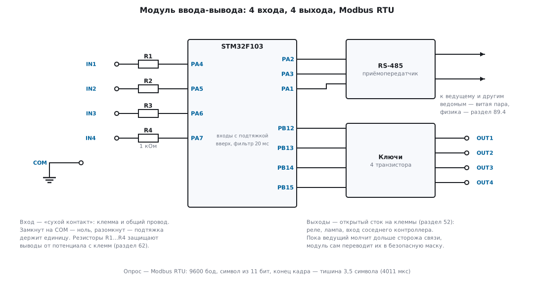
The input terminals are designed for a "dry contact" — a button, a limit switch, a relay of another device: closed to the common wire reads as zero, open — the pull-up holds a one. Series resistors protect the pins from whatever arrives from the terminals in the cabinet (section 62). The line is RS-485: a differential pair, dozens of devices, up to a kilometer; terminators, biasing and the DE pin are in section 89.4. The physics of the line is not the main point here — the model exchanges frames directly.
198в.2 The RTU frame and CRC16
A Modbus RTU frame consists of four fields: the slave address (1…247, 0 — broadcast), the function code, the data and the CRC. Here is the reference request "read two holding registers starting from zero" — all the frames that follow are built exactly the same way:
01 |
03 |
00 00 |
00 02 |
C4 0B |
|---|---|---|---|---|
| address 1 | function 03 | first register | how many | CRC |
Numbers in the data fields go most significant byte first (section 126), but the CRC goes the other way, least significant first: these are two different rules in one frame, and mixing them up is the most common cause of "the CRC does not match".
CRC-16/MODBUS from section 43: polynomial 0xA001 (reflected 0x8005),
initial value 0xFFFF:
uint16_t mbio_crc(const uint8_t *p, size_t n)
{
    uint16_t c = 0xFFFF;                /* начальное значение */
    while (n--) {
        int i;
        c ^= *p++;                      /* байт — в младшую половину */
        for (i = 0; i < 8; i++)
            c = (c & 1) ? (uint16_t)((c >> 1) ^ 0xA001)   /* отражённый 0x8005 */
                        : (uint16_t)(c >> 1);
    }
    return c;
}
The implementation is checked by running it: the string 123456789 gives 0x4B37 —
the check value of CRC-16/MODBUS; the CRC of the reference frame above is C4 0B;
the frame writing registers 17–18 from the experiment in section 16.8 gives the same bytes
A3 74 as there. The master in this project computes the CRC with its own implementation
in Python — and all the frames of the run matched the C implementation byte for byte.
198в.3 A silence of 3.5 characters
An RTU frame has neither a start byte nor a length field — frames are separated by a silence of at least 3.5 characters. A character here is 11 bits: start, 8 data bits, parity, stop (section 16.8). This gives the microseconds:
| Baud rate | Character | End of frame, 3.5 char. | Gap inside, 1.5 char. |
|---|---|---|---|
| 9600 baud | 1146 µs | 4011 µs | 1719 µs |
| 115 200 baud | 96 µs | 335 µs | 144 µs |
| above 19 200 baud | — | fixed at 1750 µs | fixed at 750 µs |
At 9600 the end of a frame is a little more than 4 ms of silence; at 115 200 it is
only 335 µs, and any hiccup of the master computer is longer, so above
19 200 baud the pauses are taken as constants rather than counted in characters. The
silence is caught as shown in section 16.8: a timer in one-pulse mode,
every received byte resets the count; when it runs out, the frame is over. At 9600 with a
1 µs tick this is ARR = 4010.
⚠️ The
IDLEflag is not the same thing. It is set after a silence of just one character (section 16.5; in HAL —ReceiveToIdle, section 5а.5). That is not enough for the end of a frame: the protocol allows a gap of up to 1.5 characters inside a frame, andIDLEwill cut such a frame in two. With a timer set to 3.5 characters, a hiccup of up to 1719 µs does not break the frame.
198в.4 The module's register map
Modbus data lives in four areas: discrete inputs, coils, input registers and holding registers. The module needs three of them — and each area has its own address table. This is the device's datasheet: to work with the module, the master needs nothing else.
| Area | Address | What is there | Functions |
|---|---|---|---|
| discrete inputs | 0…3 | IN1…IN4 after the filter | 02 — read |
| coils | 0…3 | OUT1…OUT4 | 01 — read, 05 — write |
| holding registers | 0 | input filter, ms (default 20) | 03 — read, 16 — write |
| 1 | communication watchdog, 0.1 s units (default 50, which is 5.0 s; 0 — off) | ||
| 2 | safe output mask, bits 0…3 (default 0) | ||
| 3 | counter of frames with a bad CRC |
Each area has its own addresses, starting from zero: "coil 1" and "holding register 1" are different things, and the function code tells them apart.
⚠️ Device datasheets often number from one. In the frame the address counts from zero, but documentation tables often number the points from the first. You write to "register 1" as the datasheet says, and register zero changes — a minus one got lost somewhere. Check this as well as the area: some manufacturers give the address in the frame, others the point number.
198в.5 Request → response
Frame parsing is a single portable function, mbio_frame: check the CRC and the
address, parse the fields, build the response directly in the transmit buffer (24 bytes
of stack). The skeleton is like mb_process in section 16.8; what is new here is the bit
functions. The response to "read N bits" packs the bits into bytes, with the least significant bit
being the first point, and they are preceded by the byte count:
    case 1:                                         /* чтение катушек */
    case 2:                                         /* чтение дискретных входов */
        if (broadcast)
            return 0;                               /* чтение всем сразу — бессмыслица */
        if (n != 8 || count < 1 || count > 2000) {
            k = mb_ex(resp, m->addr, fn, MBIO_EX_VALUE);
        } else if ((uint32_t)first + count > MBIO_NIO) {
            k = mb_ex(resp, m->addr, fn, MBIO_EX_ADDR);
        } else {
            uint8_t bits = (uint8_t)((fn == 1 ? m->out : m->in_state) >> first);
            resp[0] = m->addr;
            resp[1] = fn;
            resp[2] = (uint8_t)((count + 7) / 8);   /* счётчик байт */
            resp[3] = (uint8_t)(bits & ((1u << count) - 1u));
            k = mb_done(resp, 4);
        }
        break;
The limit of 2000 bits comes from the 256-byte frame: 2000 bits are 250 bytes of data, and the response takes exactly 255 bytes, just like reading 125 registers with function 03 or writing 123 registers with function 16.
Writing a single coil — function 05 — has two peculiarities. There are
only two values, and they are encoded not as 0 and 1 but as 0x0000 and 0xFF00 — anything
else gets exception 03. And the response is an echo: the same eight bytes
that came in the request:
            if (count == 0xFF00)
                m->out |= (uint8_t)(1u << first);
            else
                m->out &= (uint8_t)~(1u << first);
            for (k = 0; k < 6; k++)
                resp[k] = req[k];                   /* ответ — эхо запроса */
            k = mb_done(resp, 6);
Settings are written with function 16 into the holding registers — the parsing is exactly as in 16.8, only there are four registers. The module answers errors according to the protocol: whether it stays silent or objects depends on whether the frame arrived intact.
| What arrived | What the module does |
|---|---|
| a frame with a bad CRC or a fragment | stays silent and increments the counter in register 3 |
| someone else's address | stays silent |
| address 0 — broadcast | executes the write, never answers |
| a function not in the table | exception 01 |
| a point outside the area | exception 02 |
| an invalid value or length | exception 03 |
An exception response is three bytes before the CRC: the address, the function with the most significant bit set, and the reason code.
198в.6 Input filter and communication watchdog
Input filter. Limit switches and relays bounce, and the master polls rarely — it must not catch the bounce. An input is accepted at a new level only if it has held for the "filter time" (register 0, default 20 ms) without a single glitch:
        if (((m->in_raw ^ m->in_state) & bit) == 0) {
            m->in_cnt[i] = 0;                     /* согласие — счёт заново */
        } else {
            uint32_t c = m->in_cnt[i] + ms;
            if (c >= m->hold[MBIO_H_FILTER]) {    /* продержался — признан */
                m->in_state ^= bit;
                m->in_cnt[i] = 0;
            } else {
                m->in_cnt[i] = (uint16_t)c;
            }
        }
An experiment on the model: the input bounces with a glitch every 3 ms, the last glitch is at the 12th millisecond; the one is accepted at the 32nd — exactly 20 ms after the last glitch, and not a single intermediate spike got out.
Communication watchdog. An output that the master switched on and then disappeared — with a broken line or a frozen computer — would stay on forever. That is why real modules have a watchdog: if there is no valid frame to our address for longer than the time in register 1, the outputs take the safe mask from register 2. Frames for other addresses and frames with a bad CRC do not feed the watchdog: noise on the line is not a sign of a live master.
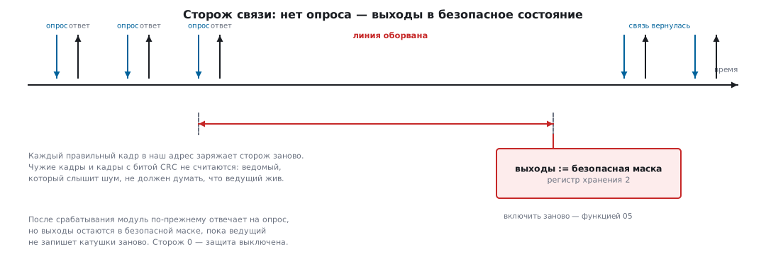
The experiment: the master switched coil 1 on and fell silent. For 4999 ms the output holds; at the
5000th millisecond the outputs change from 0x02 to 0x00. The link
itself is still alive: the module answers the next request as if nothing had happened —
01 01 01 00 51 88, the coils are zeros — and the master sees from the response that it is
time to write the outputs again.
198в.7 The master on a computer and the joint run
The master is master.py, with no ready-made Modbus libraries: the frame is built from the
address, the function and the data, and the CRC is its own implementation in Python:
def frame(addr, fn, payload):
    """Кадр RTU: адрес, функция, данные, CRC младшим байтом вперёд."""
    body = bytes([addr, fn]) + payload
    c = crc16(body)
    return body + bytes([c & 0xFF, c >> 8])
With a real port, the end of the response is caught by the same silence that separates frames — reading with a timeout between bytes:
    def xfer(self, req):
        self.s.reset_input_buffer()
        self.s.write(req)
        resp = b""
        while True:
            b = self.s.read(1)               # нет байта дольше 50 мс — кадр кончился
            if not b:
                return resp
            resp += b
For the run, the port is replaced by a model of the slave on the computer: the same
mbio.c bytes wrapped in slave_pipe.c. The master ran a scenario of
14 exchanges: normal reads and writes, all three exceptions, a bad CRC,
someone else's address, a broadcast and the watchdog. The log is master_host.txt; here are its
typical lines:
# чтение дискретных входов 0…3 — функция 02
-> 01 02 00 00 00 04 79 C9
<- 01 02 01 05 61 8B
# включить катушку 1 — функция 05, значение FF00
-> 01 05 00 01 FF 00 DD FA
<- 01 05 00 01 FF 00 DD FA
# чтение регистров 100…101 — таких нет
-> 01 03 00 64 00 02 85 D4
<- 01 83 02 C0 F1
In the first response the byte count is 01 and the byte is 05 — IN1 and IN3 are closed;
in the second it is the echo; in the third, function 83 and code 02. Further down the log:
| What the master sent | The module's response |
|---|---|
| reading the coils after switching the first one on | byte 02 |
| reading holding registers 0…3 | 20, 50, 0, 0 — defaults |
| setup: filter 10 ms, watchdog 3.0 s (function 16) | acknowledgment |
| a frame with a corrupted CRC | silence; register 3 became 1 |
| a request to address 5 | silence |
| function 04 — the module has no input registers | exception 01 |
coil 2, value 0x1234 |
exception 03 |
| broadcast write of coil 3 | silence; a read gives 0A |
| 3.0 s without polls | outputs 0A → 00, the watchdog tripped |
The result of the run: 14 exchanges, 3 legitimate silences, 3 exceptions, not a single
deviation from the expectation — done=1 in the log.
198в.8 Porting to the board and what to improve
The platform for the BluePill is exactly the recipe from section 16.8: USART2 on PA2 and
PA3, 9600 baud 8E1 (BRR = 3750 from 36 MHz — no error), TIM2 with a
1 µs tick and ARR = 4010 for the pause, the transceiver's DE driven by the
TC flag. All that is left for the logic is to pass the frame to mbio_frame, call
mbio_tick once a millisecond and copy out to the switch pins.
The logic built with arm-none-eabi-gcc -Os for Cortex-M3: 770 bytes of code,
not a single byte of static data — the whole state of the module lives in one
structure of 28 bytes, and the deepest function takes 24 bytes of stack.
A chip like this could host a dozen modules — one structure per address.
What to improve:
- Functions 06 and 15 — writing a single register and multiple coils: the parsing is the same, and masters use them often.
- Bit mirrors in holding registers: inputs and outputs as one word — for masters that can only do function 03.
- Input registers with counters of input edges: if a limit switch managed to trip between polls, the counter shows it, while an instantaneous read does not.
- Address and baud rate from jumpers or a DIP switch at startup: reflashing a module just to change its bus address is tedious.
- CRC in the hardware unit (section 43) — noticeable on long frames.
198в.9 Pitfalls
The CRC "does not match" on any frame. Byte order: the data fields in the
frame go most significant byte first, but the CRC least significant first. Reference: 01 03 00 00
00 02 ends with C4 0B, not 0B C4.
The slave is silent on valid frames. Parity: an RTU character is 11 bits with a parity bit, but the master's port is opened as 8N1. Every character arrives with a parity error — and the frame honestly goes into the bin.
Frames get cut or glued together. The end of the frame is caught by IDLE — a silence
of one character: a gap of 1.5 characters inside a frame, which the protocol
allows, cuts the frame in two. And the other way round: at 115 200 baud, counting the pauses
in characters means taking a hiccup of the master for the end of a frame; above
19 200 baud the pauses are taken as constants.
Wrote to coil 1 — exception 03. The value for function 05 is only
0xFF00 or 0x0000. A one, like any other number, is an invalid
value.
You write to a point from the datasheet — the neighboring one changes. Numbering: in the frame addresses start from zero, in device datasheets often from one. A minus one — and the write goes to the wrong place or gets exception 02.
A broadcast write "does not work". It works — silently: nobody answers address 0, otherwise all the slaves would collide on the line at once. Check it with a subsequent read.
The outputs switched off by themselves in the middle of operation. The communication watchdog: the master started polling less often than the watchdog is set to — and the module honestly went to the safe mask. Either poll more often or increase the time in register 1.
198в.10 Summary
- An I/O module = a register map + frame parsing + a communication watchdog; the logic is 770 bytes of code, the state is a 28-byte structure, the stack is 24 bytes.
- An RTU frame: address, function, data most significant byte first, CRC-16/MODBUS
least significant first; polynomial
0xA001from0xFFFF, check value123456789→ 0x4B37. - Frames are separated by a silence of 3.5 characters: 4011 µs at 9600 baud, 335 µs at
115 200; above 19 200 baud a constant 1750 µs. Catch it with a timer, not with
IDLE. - Bit functions pack points into bytes with a byte count; the limits of 2000 bits and 125/123 registers come from the 256-byte frame.
- The 20 ms input filter: a level is accepted 20 ms after the last bounce glitch; the 5.0 s communication watchdog put the outputs into the safe mask at the 5000th millisecond of silence.
- The joint run with the Python master: 14 exchanges, 3 silences, 3 exceptions; the CRCs of two independent implementations matched byte for byte.
Full source code
mbio.c — the logic of the Modbus RTU I/O module.
/* mbio.c — логика модуля ввода-вывода Modbus RTU.
 * Функции: 01 чтение катушек, 02 чтение дискретных входов, 03 чтение
 * регистров хранения, 05 запись одной катушки, 16 запись регистров. */
#include "mbio.h"

void mbio_init(struct mbio *m, uint8_t addr)
{
    unsigned i;
    m->addr = addr;
    m->in_raw = m->in_state = m->out = 0;
    m->wd_tripped = 0;
    m->idle_ms = 0;
    for (i = 0; i < MBIO_NIO; i++)
        m->in_cnt[i] = 0;
    m->hold[MBIO_H_FILTER] = 20;    /* фильтр входов 20 мс */
    m->hold[MBIO_H_WDOG]   = 50;    /* сторож связи 5,0 с */
    m->hold[MBIO_H_SAFE]   = 0;     /* безопасное состояние: всё выключено */
    m->hold[MBIO_H_CRCERR] = 0;
}

void mbio_input(struct mbio *m, uint8_t raw)
{
    m->in_raw = raw & 0x0F;
}

void mbio_tick(struct mbio *m, uint32_t ms)
{
    unsigned i;
    for (i = 0; i < MBIO_NIO; i++) {
        uint8_t bit = 1u << i;
        if (((m->in_raw ^ m->in_state) & bit) == 0) {
            m->in_cnt[i] = 0;                     /* согласие — счёт заново */
        } else {
            uint32_t c = m->in_cnt[i] + ms;
            if (c >= m->hold[MBIO_H_FILTER]) {    /* продержался — признан */
                m->in_state ^= bit;
                m->in_cnt[i] = 0;
            } else {
                m->in_cnt[i] = (uint16_t)c;
            }
        }
    }
    if (m->idle_ms < 0xFFFFFFFFu - ms)
        m->idle_ms += ms;
    if (m->hold[MBIO_H_WDOG] != 0 && !m->wd_tripped
        && m->idle_ms >= 100u * m->hold[MBIO_H_WDOG]) {
        m->out = (uint8_t)(m->hold[MBIO_H_SAFE] & 0x0F);
        m->wd_tripped = 1;
    }
}

uint16_t mbio_crc(const uint8_t *p, size_t n)
{
    uint16_t c = 0xFFFF;                /* начальное значение */
    while (n--) {
        int i;
        c ^= *p++;                      /* байт — в младшую половину */
        for (i = 0; i < 8; i++)
            c = (c & 1) ? (uint16_t)((c >> 1) ^ 0xA001)   /* отражённый 0x8005 */
                        : (uint16_t)(c >> 1);
    }
    return c;
}

static uint16_t be16(const uint8_t *p)   /* поля кадра — старшим байтом вперёд */
{
    return (uint16_t)(p[0] << 8 | p[1]);
}

static size_t mb_done(uint8_t *r, size_t n)   /* CRC — младшим байтом вперёд */
{
    uint16_t c = mbio_crc(r, n);
    r[n] = (uint8_t)c;
    r[n + 1] = (uint8_t)(c >> 8);
    return n + 2;
}

static size_t mb_ex(uint8_t *r, uint8_t addr, uint8_t fn, uint8_t code)
{
    r[0] = addr;
    r[1] = (uint8_t)(fn | 0x80);        /* функция с поднятым старшим битом */
    r[2] = code;
    return mb_done(r, 3);
}

size_t mbio_frame(struct mbio *m, const uint8_t *req, size_t n, uint8_t *resp)
{
    uint8_t fn;
    uint16_t first, count;
    int broadcast;
    size_t k;

    if (n < 4 || n > MBIO_ADU)
        return 0;                                   /* обрезок — молчать */
    if (mbio_crc(req, n - 2) != (uint16_t)(req[n - 2] | (req[n - 1] << 8))) {
        m->hold[MBIO_H_CRCERR]++;                   /* битая CRC — молчать */
        return 0;
    }
    broadcast = req[0] == 0;
    if (!broadcast && req[0] != m->addr)
        return 0;                                   /* чужой адрес — молчать */
    m->idle_ms = 0;                                 /* кадр нам — сторож заново */
    m->wd_tripped = 0;
    fn = req[1];
    first = n >= 8 ? be16(req + 2) : 0;
    count = n >= 8 ? be16(req + 4) : 0;

    switch (fn) {
    case 1:                                         /* чтение катушек */
    case 2:                                         /* чтение дискретных входов */
        if (broadcast)
            return 0;                               /* чтение всем сразу — бессмыслица */
        if (n != 8 || count < 1 || count > 2000) {
            k = mb_ex(resp, m->addr, fn, MBIO_EX_VALUE);
        } else if ((uint32_t)first + count > MBIO_NIO) {
            k = mb_ex(resp, m->addr, fn, MBIO_EX_ADDR);
        } else {
            uint8_t bits = (uint8_t)((fn == 1 ? m->out : m->in_state) >> first);
            resp[0] = m->addr;
            resp[1] = fn;
            resp[2] = (uint8_t)((count + 7) / 8);   /* счётчик байт */
            resp[3] = (uint8_t)(bits & ((1u << count) - 1u));
            k = mb_done(resp, 4);
        }
        break;
    case 3:                                         /* чтение регистров хранения */
        if (broadcast)
            return 0;
        if (n != 8 || count < 1 || count > 125) {
            k = mb_ex(resp, m->addr, fn, MBIO_EX_VALUE);
        } else if ((uint32_t)first + count > MBIO_NHOLD) {
            k = mb_ex(resp, m->addr, fn, MBIO_EX_ADDR);
        } else {
            uint16_t i;
            resp[0] = m->addr;
            resp[1] = fn;
            resp[2] = (uint8_t)(2 * count);
            for (i = 0; i < count; i++) {
                resp[3 + 2 * i] = (uint8_t)(m->hold[first + i] >> 8);
                resp[4 + 2 * i] = (uint8_t)m->hold[first + i];
            }
            k = mb_done(resp, 3u + 2u * count);
        }
        break;
    case 5:                                         /* запись одной катушки */
        if (n != 8 || (count != 0x0000 && count != 0xFF00)) {
            k = mb_ex(resp, m->addr, fn, MBIO_EX_VALUE);   /* только FF00 и 0000 */
        } else if (first >= MBIO_NIO) {
            k = mb_ex(resp, m->addr, fn, MBIO_EX_ADDR);
        } else {
            if (count == 0xFF00)
                m->out |= (uint8_t)(1u << first);
            else
                m->out &= (uint8_t)~(1u << first);
            for (k = 0; k < 6; k++)
                resp[k] = req[k];                   /* ответ — эхо запроса */
            k = mb_done(resp, 6);
        }
        break;
    case 16:                                        /* запись регистров хранения */
        if (n < 9 || count < 1 || count > 123
            || req[6] != 2 * count || n != 9u + req[6]) {
            k = mb_ex(resp, m->addr, fn, MBIO_EX_VALUE);
        } else if ((uint32_t)first + count > MBIO_NHOLD) {
            k = mb_ex(resp, m->addr, fn, MBIO_EX_ADDR);
        } else {
            uint16_t i;
            for (i = 0; i < count; i++)
                m->hold[first + i] = be16(req + 7 + 2 * i);
            for (i = 0; i < 6; i++)                 /* адрес, функция, первый, число */
                resp[i] = req[i];
            k = mb_done(resp, 6);
        }
        break;
    default:
        k = mb_ex(resp, m->addr, fn, MBIO_EX_FUNC);
        break;
    }
    return broadcast ? 0 : k;                       /* на широковещание не отвечают */
}
master.py — a Modbus RTU master on a computer.
# -*- coding: utf-8 -*-
"""master.py — ведущий Modbus RTU: опрос модуля ввода-вывода.

python3 master.py --pipe ./mbslave   прогон против модели модуля на компьютере
python3 master.py --port COM7        то же по настоящему порту (нужен pyserial)
"""
import subprocess
import sys


def crc16(data):
    """CRC-16/MODBUS: полином 0xA001 (отражённый 0x8005), начальное 0xFFFF."""
    c = 0xFFFF
    for b in data:
        c ^= b
        for _ in range(8):
            c = (c >> 1) ^ 0xA001 if c & 1 else c >> 1
    return c


def frame(addr, fn, payload):
    """Кадр RTU: адрес, функция, данные, CRC младшим байтом вперёд."""
    body = bytes([addr, fn]) + payload
    c = crc16(body)
    return body + bytes([c & 0xFF, c >> 8])


def be(x):
    return bytes([x >> 8, x & 0xFF])


def hx(b):
    return " ".join("%02X" % x for x in b)


class PipeLink:
    """Модель модуля на компьютере — обмен строками через канал."""

    def __init__(self, path):
        self.p = subprocess.Popen([path], stdin=subprocess.PIPE,
                                  stdout=subprocess.PIPE, text=True)

    def cmd(self, line):
        self.p.stdin.write(line + "\n")
        self.p.stdin.flush()
        return self.p.stdout.readline().strip() if line[0] in "RO" else ""

    def xfer(self, req):
        r = self.cmd("R " + req.hex(" "))
        r = r[2:].strip()
        return b"" if r == "-" else bytes.fromhex(r)


class SerialLink:
    """Настоящий порт: конец ответа — та же тишина, что делит кадры."""

    def __init__(self, port, baud=9600):
        import serial                        # pyserial
        self.s = serial.Serial(port, baud, bytesize=8,
                               parity="E", stopbits=1, timeout=0.05)

    def xfer(self, req):
        self.s.reset_input_buffer()
        self.s.write(req)
        resp = b""
        while True:
            b = self.s.read(1)               # нет байта дольше 50 мс — кадр кончился
            if not b:
                return resp
            resp += b


fails = 0


def poll(link, note, addr, fn, payload, expect):
    """Один обмен: запрос, ответ (или тишина), сверка с ожиданием."""
    global fails
    req = frame(addr, fn, payload)
    print("# " + note)
    print("-> " + hx(req))
    resp = link.xfer(req)
    print("<- " + (hx(resp) if resp else "тишина"))
    if resp != expect:
        print("ОЖИДАЛОСЬ: " + (hx(expect) if expect else "тишина"))
        fails += 1
    return resp


def main():
    if len(sys.argv) == 3 and sys.argv[1] == "--pipe":
        link = PipeLink(sys.argv[2])
    elif len(sys.argv) == 3 and sys.argv[1] == "--port":
        link = SerialLink(sys.argv[2])
    else:
        sys.exit("нужно: --pipe <модель> или --port <порт>")

    silent = exceptions = 0

    if isinstance(link, PipeLink):
        link.cmd("I 5")                      # на клеммах входы 1 и 3
        link.cmd("T 100")                    # фильтр 20 мс успел отработать
        print("(входы модуля: IN1 и IN3 замкнуты, прошло 100 мс)")

    poll(link, "чтение дискретных входов 0…3 — функция 02",
         1, 2, be(0) + be(4), frame(1, 2, bytes([1, 0x05])))
    poll(link, "включить катушку 1 — функция 05, значение FF00",
         1, 5, be(1) + bytes([0xFF, 0]), frame(1, 5, be(1) + bytes([0xFF, 0])))
    poll(link, "чтение катушек 0…3 — функция 01",
         1, 1, be(0) + be(4), frame(1, 1, bytes([1, 0x02])))
    poll(link, "чтение регистров хранения 0…3 — функция 03",
         1, 3, be(0) + be(4),
         frame(1, 3, bytes([8]) + be(20) + be(50) + be(0) + be(0)))
    poll(link, "настройка: фильтр 10 мс, сторож 3,0 с — функция 16",
         1, 16, be(0) + be(2) + bytes([4]) + be(10) + be(30),
         frame(1, 16, be(0) + be(2)))

    print("# кадр с испорченной CRC — модуль обязан молчать")
    bad = bytearray(frame(1, 3, be(0) + be(1)))
    bad[-1] ^= 0xFF
    print("-> " + hx(bad))
    resp = link.xfer(bytes(bad))
    print("<- " + (hx(resp) if resp else "тишина"))
    silent += resp == b""

    resp = poll(link, "запрос к адресу 5 — на шине такого нет",
                5, 3, be(0) + be(1), b"")
    silent += resp == b""
    poll(link, "чтение регистра 3 — счётчик кадров с битой CRC",
         1, 3, be(3) + be(1), frame(1, 3, bytes([2]) + be(1)))
    r = poll(link, "чтение регистров 100…101 — таких нет",
             1, 3, be(100) + be(2), frame(1, 0x83, bytes([2])))
    exceptions += len(r) == 5
    r = poll(link, "функция 04: регистров ввода у модуля нет",
             1, 4, be(0) + be(1), frame(1, 0x84, bytes([1])))
    exceptions += len(r) == 5
    r = poll(link, "катушка 2, значение 1234 — не FF00 и не 0000",
             1, 5, be(2) + be(0x1234), frame(1, 0x85, bytes([3])))
    exceptions += len(r) == 5
    r = poll(link, "широковещательная запись: адрес 0, катушка 3 — FF00",
             0, 5, be(3) + bytes([0xFF, 0]), b"")
    silent += r == b""
    poll(link, "чтение катушек: широковещательная запись выполнена молча",
         1, 1, be(0) + be(4), frame(1, 1, bytes([1, 0x0A])))

    if isinstance(link, PipeLink):
        link.cmd("T 3000")                   # опросы прекратились на 3,0 с
        print("(3,0 с без опросов: " + link.cmd("O") + ")")
    poll(link, "после сторожа: выходы в безопасном состоянии, связь живёт",
         1, 1, be(0) + be(4), frame(1, 1, bytes([1, 0x00])))

    if isinstance(link, PipeLink):
        link.cmd("Q")
    print("exchanges=14 silent=%d exceptions=%d fails=%d" %
          (silent, exceptions, fails))
    if fails == 0:
        print("done=1")
    sys.exit(1 if fails else 0)


if __name__ == "__main__":
    main()
Next: section 198г "Mini-project: gestures from an accelerometer".