 Embedded HandbookApps
198д. Mini-project: a logic analyzer made from a BluePill
The last mini-project is a measuring instrument. Section 36а lists a logic analyzer among the instruments on your desk; until you have one, the BluePill itself can play the role of an eight-channel pod: a timer sets the sample rate, DMA moves the port into a ring buffer, UART sends the record to the computer, and Python parses it and turns it into a file for a viewer program. Along the way there is honest arithmetic: what sample-rate ceiling follows from the bus architecture, how many milliseconds fit into 20 KB of RAM and how many seconds the upload takes.
This is an instrument "until you have the instrument": the store-bought pod from section 36а.6 records 8 channels at 24 MS/s for hours on end, while our home-made one captures 16384 samples and no faster than 4.5 MS/s. In return, it shows how a logic analyzer works inside, down to the pre-trigger record and the trigger mark.
The files are in _verify/la198d/: la_f103.c (firmware), start_f103.c,
la_host.py (capture model, parser and VCD converter). The firmware is
built for Cortex-M3, and the model was run on the computer with a self-test.
The check is _verify/la198d_check.py.
Terms used in the documentation
Term Meaning memory depth, capture depth how many samples fit into the instrument's memory armed recording is already running, the instrument waits for the trigger condition post-trigger the part of the buffer after the trigger moment metastability a latch "stuck" between 0 and 1 synchronizer two latches in a row on an asynchronous input value change dump (VCD) a text format for signal records: the moments of transitions run-length encoding (RLE) storing the durations of levels bus matrix the arbiter between the CPU and DMA
198д.1 What the instrument does and what it cannot do
| Function | How |
|---|---|
| eight channels | PB0…PB7: the low byte of GPIOB->IDR, one sample = one byte |
| sample rate | a grid of 100 kS/s … 4.5 MS/s from TIM2 (crystal ×9 = 72 MHz) |
| capture depth | a ring of 16384 samples, 16.4 ms at 1 MS/s |
| trigger | a rising or falling edge on any of the channels, via EXTI |
| pre-trigger | a quarter of the ring: the history before the edge, for free |
| upload | USART1: 115200 or 921600 baud, our own "LA1" format |
| on the computer | timing diagram, UART decoding, VCD converter for PulseView |
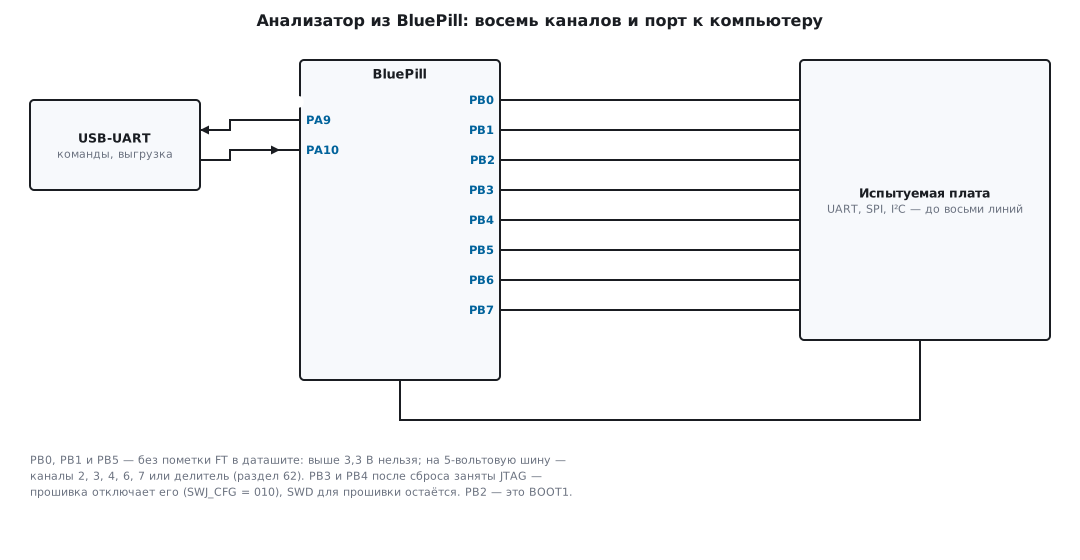
The channels are the whole low byte of port B. Two pins have quirks: PB2 is
BOOT1 (on the BluePill it goes to a jumper through a resistor; this weak divider
does not disturb the signal), and PB3 and PB4 belong to JTAG after reset. The firmware
disables JTAG in the very first line of setup (SWJ_CFG = 010 in AFIO_MAPR:
"JTAG-DP disabled, SW-DP enabled"), so you can still flash over SWD
as before, and PB3 and PB4 become ordinary inputs.
⚠️ Three channels out of eight do not tolerate 5 V. In the pin table of the F103 datasheet, PB0, PB1 and PB5 have no FT mark: their limit is VDD + 0.3 V. The FT inputs (the other five channels) withstand up to 5.5 V. Connect a five-volt bus to channels 2, 3, 4, 6, 7, or through a divider (section 62). This also applies to I²C with pull-ups to 5 V.
What you can examine is decided by the rule from section 36а.6: no fewer than four to five samples per bit. At 1 MS/s that is UART 115200 (8.7 samples per bit, with margin), at 4.5 MS/s it is SPI and I²C up to hundreds of kilohertz. For buses running at megahertz and for hunting nanosecond glitches you need a real instrument or an oscilloscope (section 36а).
198д.2 The sample-rate ceiling: counting by the buses
The path of one sample: TIM2 reaches the end of its count, an update event,
a DMA request, DMA reads GPIOB->IDR, writes a byte to RAM. Before
promising megahertz, let us count what this path costs.
- Port B sits on APB2, the AHB/APB bridge runs synchronously, and our APB2 runs at the full 72 MHz. A read through the bridge takes at least two clocks: an address clock and a data clock; that is how the APB bus works.
- Writing a byte to RAM is one more AHB clock.
- The reference manual reminds you that each DMA transfer is three operations (source read, destination write, counter update), plus arbitration on the bus matrix. Another two or three clocks of overhead.
In total a sample takes at least five clocks at 72 MHz, a ceiling of about 14 MS/s, and only if the DMA is alone on the bus. It is not alone: the bus matrix shares access round-robin and guarantees the CPU at least half of the bandwidth, which means that in the worst case the DMA gets only half too. That is why the top step of the grid is 4.5 MS/s: 16 clocks per sample, a threefold margin over the calculated five. We do not promise anything faster: the DMA will not report a missed sample in any way (198д.9), and "an analyzer that sometimes lies" is worse than none. During the capture the CPU stays out of the way: it only reads the DMA counter.
Memory is simpler to count. One sample is a byte, the ring is 16 KB out of 20 KB of RAM (the rest is the stack and variables; giving it all 20 KB = 20.5 ms will not work):
| Sample rate | Ring of 16384 samples | Clocks per sample |
|---|---|---|
| 4.5 MS/s | 3.6 ms | 16 |
| 1 MS/s | 16.4 ms | 72 |
| 500 kS/s | 32.8 ms | 144 |
| 100 kS/s | 164 ms | 720 |
198д.3 Capture: the timer sets the step, DMA carries the bytes
The sample rate is set by TIM2: ARR = 72 MHz / f − 1, and every update
event issues a DMA request (the UDE bit in DIER; timers themselves are section 13,
the map of "which request is on which channel" is section 9: TIM2_UP is served by
channel 2 of DMA1). The channel is configured like this:
    DMA1_Channel2->CPAR = (uint32_t)&GPIOB->IDR;  /* источник: порт B, чтение словом */
    DMA1_Channel2->CMAR = (uint32_t)ring;
    DMA1_Channel2->CNDTR = N;
    DMA1_Channel2->CCR = DMA_CCR2_PSIZE_1 | DMA_CCR2_MINC | DMA_CCR2_CIRC | DMA_CCR2_EN;
Two non-obvious widths. GPIO registers on the F1 must be read only as
32-bit words, so the source is declared 32-bit (PSIZE_1),
while the destination is byte-wide: according to the width table in the reference manual, DMA
in this case writes the low byte of the word it read to memory, which is exactly
PB0…PB7. One request, one byte of the ring, and the CPU takes no part.
Then the capture itself starts:
    TIM2->ARR = (uint16_t)(FCLK / rates[rate_i] - 1u);
    TIM2->EGR = TIM_EGR_UG;                       /* применить ARR сразу */
    TIM2->DIER = TIM_DIER_UDE;                    /* запрос DMA по событию обновления */
    TIM2->CR1 = TIM_CR1_CEN;                      /* выборки пошли */
🔧 Recipe: check the sample grid with a square wave. Set up a PWM on PA8 at 100 kHz with a 50 % duty cycle (section 13.5) and feed it with a jumper to channel 7. In the record at 1 MS/s the period must be exactly 10 samples; if you get 11–12 "every other time", samples are being lost and the sample rate must be lowered. It is worth greeting every new rate with such a self-check.
198д.4 Trigger: wait for the edge without losing the beginning
The naive plan "we saw the edge, start recording" loses the most interesting part: what happened before the edge, and you often want to see, for example, the state of the lines before a transfer starts. The solution of all real analyzers is to record always: the DMA runs in circular mode (section 9) and spins the ring round and round before any trigger at all. The edge starts nothing; it only sets a mark.
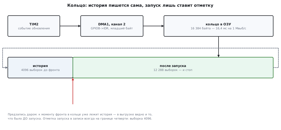
The edge is caught by EXTI (section 7): the line by channel number, port B, rising or falling edge. The handler is tiny:
void EXTI_IRQHandler(void)
{
    trig_ndtr = DMA1_Channel2->CNDTR;   /* где кольцо было в момент фронта */
    EXTI->PR = 0xFFu;                   /* снять запросы */
    EXTI->IMR &= ~0xFFu;                /* второй фронт уже не нужен */
    triggered = 1;
}
The order is this: after arming, the firmware first lets the ring accumulate the pre-trigger record (a quarter of the ring, 4096 samples) and only then enables EXTI. After the edge the remaining 12288 samples are written, and the timer stops. That is why in the uploaded record the trigger mark always sits exactly at sample 4096, with the real input history before it.
The mark is not perfect: interrupt entry takes 12 clocks plus tails (section 7),
and CNDTR is read with a delay. At 4.5 MS/s (16 clocks per sample)
the mark can drift by one or two samples, while the data itself is not
distorted by a single bit: it is written by the DMA, which does not care about interrupts.
198д.5 Upload: our own format and how long to wait
After the stop the ring is unrolled in time, from the oldest sample to the newest, and goes to USART1 with a 16-byte header:
| Bytes | What |
|---|---|
| 0…3 | LA1 and the format version (1) |
| 4…7 | sample rate, Hz |
| 8…11 | number of samples (16384) |
| 12…15 | index of the sample with the trigger mark |
    uint32_t start = (N - DMA1_Channel2->CNDTR) & (N - 1u);  /* самая старая выборка */
    uint32_t trig = (N - trig_ndtr) & (N - 1u);              /* выборка момента запуска */
    for (uint32_t i = 0; i < N; i++)
        tx(ring[(start + i) & (N - 1u)]);         /* кольцо — по порядку времени */
The upload is (16 + 16384) bytes at 10 bits per byte, 164000 bits:
| Port speed | BRR divider | Actual | Upload time |
|---|---|---|---|
| 115200 baud | 625 | exactly 115200 | 1.42 s |
| 921600 baud | 78 | 923077 baud (+0.16 %) | 0.18 s |
Exactly 921600 cannot be divided out of 72 MHz: the nearest integer divider 78 gives
923077 baud; an error of 0.16 % is unnoticeable for UART (the tolerance is about 2 %,
section 16). Commands to the instrument are single bytes: 0…7 is the trigger channel,
a/A arms on a falling/rising edge, g captures unconditionally,
s selects the next sample rate, u toggles the port speed.
The build with arm-none-eabi-gcc -Os for Cortex-M3 has no warnings:
1272 bytes of Flash and 16396 bytes of RAM, of which 16384 are the ring.
The firmware is the junior partner: almost all the work rests on the DMA and the computer.
198д.6 Analysis on the computer: diagram, UART and VCD
The computer half is la_host.py. It reads the upload and prints
a piece of the timing diagram around the trigger mark:
к0  ▔▔▔▔▔▔▔▔▁▁▁▁▁▁▁▁▁▁▁▁▁▁▁▁▁▁▁▁▁▁▁▁
к1  ▁▁▔▔▔▔▔▔▔▔▔▔▁▁▁▁▁▁▁▁▁▁▔▔▔▔▔▔▔▔▔▔
            ^ запуск (выборка 4096)
and decodes UART: start on the falling edge, each bit is read in its middle:
        if prev == 1 and cur == 0:                    # старт-бит
            byte = 0
            for bit in range(8):
                p = k + (1.5 + bit) * spb             # середина бита данных
After the stop bit the decoder jumps to its middle and waits for the real edge of the next start: resynchronization on every byte, as in a live UART receiver (section 16). Without it, a transmitter running 2 % fast would drift by 1.7 samples per frame, and by the fifth byte the decoding would fall apart.
The same script is a converter to VCD: a text format of "moments of transitions and new values" that PulseView (section 36а.6) opens as an import, and so the record of the home-made instrument goes into the same protocol decoders as the record of a store-bought one:
$timescale 1 ns $end
$var wire 1 ! k0 $end
...
#4096000
0!
Self-test. The model in la_host.py repeats the firmware algorithm one
to one: the ring, the pre-trigger record, the edge, the mark, the "LA1" upload. A generator
feeds a UART 115200 message to channel 0 at 1 MS/s in 20 different phases
relative to the sample grid, and the record is run through the decoder:
phases 20/20 байт-в-байт, посылка b'la198d' (6 байт)
mark=[4096] (предзапись ровно PRE)
tx+2%: 20/20
All 20 phases are decoded byte for byte, the trigger mark in each record is at sample 4096, and before it there is line idle (the history is intact). With a transmitter running 2 % fast it is also 20 out of 20: the margin of 8.7 samples per bit works.
198д.7 Limitations, honestly
- The sampling moment jitters. A sample happens not on the timer clock but at the moment the DMA gets to reading the port: between the request and the read there is synchronization and arbitration, and this offset wanders by several clocks of 14 ns. At 1 MS/s it is unnoticeable, at 4.5 MS/s it is already percent of the period. Plus the usual quantization: any edge is known to within ±1 sample (section 36а.6).
- The input is asynchronous. An edge that arrives right at the sampling moment can be latched "between 0 and 1": metastability. For examining protocols this is not a problem, the bit shifts by one sample; real instruments put a synchronizer at the input, two latches in a row.
- The threshold is not adjustable. The inputs read levels by the rules of their port (section 8): for 1.8 V logic you need an instrument with an adjustable threshold, from section 36а.
- The record is finite. 16384 samples, then a pause for the upload: a rare event is caught with an edge trigger, not with a long record.
198д.8 What to improve
- Run-length encoding (RLE): store not samples but pairs of "level, duration". Slow buses with long pauses fit into the same ring tens of times deeper.
- Streaming at low rates: 923077 baud is 92300 bytes/s, so the stream covers sampling up to about 90 kS/s. Add a step of 50 kS/s and write to the computer without stopping, with the depth limited only by the disk.
- USB instead of UART (section 20): the F103 has USB, so the upload is many times faster and needs no adapter.
- Sixteen channels: a half-word DMA destination, the whole port B; the ring depth then drops by half.
198д.9 Pitfalls
Channels 3 and 4 are silent or read garbage. PB3 and PB4 belong to JTAG
after reset. Disable JTAG (SWJ_CFG = 010); SWD for flashing
remains.
Random "activity" on unconnected channels. An input without a pull resistor floats and picks up interference (section 8). This is not a signal; pulling up all eight inputs is not a good idea, since a pull-up loads the line under test.
A 100 kHz square wave "floats" in the record: a period of 10 samples, then 12. The sample rate is higher than the DMA can serve: a timer request arrived while the previous one had not finished, the sample silently vanished, and there is no error flag. Stick to the justified grid and check it with a square wave (recipe in 198д.3).
You armed it, but an edge right after the command was missed. The firmware first accumulates the pre-trigger record (4096 samples: at 100 kS/s that is 41 ms) and only then enables EXTI. This is the price of a guaranteed history before the trigger.
UART in the record decodes only every other time. Too few samples per bit: the rule from section 36а.6 is no fewer than four to five, and if the transmitter is clocked from an RC oscillator (±2 %), with margin. Raise the sample rate.
After a session on a 5 V bus the board started to get hot. PB0, PB1 or PB5 have no FT: 5 V on them is beyond the absolute maximum rating of the datasheet. Five-volt signals go only to FT channels or through a divider (section 62).
198д.10 Summary
- Analyzer = TIM2 (sample rate) + DMA into a ring (recording) + EXTI (trigger mark) + UART (upload) + Python (analysis and VCD).
- The ceiling comes from the buses: at least five clocks per sample → about 14 MS/s in the ideal case; we promise 4.5 MS/s, 16 clocks per sample, a threefold margin.
- A ring of 16384 samples: 16.4 ms at 1 MS/s; the pre-trigger record is a quarter of the ring, the trigger mark is always at sample 4096.
- Upload of 164000 bits: 1.42 s at 115200 baud and 0.18 s at 921600 (divider 78, actually 923077 baud, error 0.16 %).
- Model self-test: 20 phases byte for byte, and with a +2 % transmitter also 20/20.
- Firmware: 1272 bytes of Flash, 16396 bytes of RAM; channels PB0, PB1, PB5 are 3.3 V only, the other five are FT up to 5.5 V.
Full source code
la_f103.c: the analyzer firmware for the BluePill, capturing eight channels and uploading.
/* Мини-проект «Логический анализатор»: BluePill (STM32F103C8), регистры через CMSIS.
 *   PB0…PB7 — восемь каналов (PB0, PB1, PB5 — не FT: только до 3,3 В);
 *   PA9/PA10 — USART1: команды и выгрузка, 115 200 или 921 600 бод.
 * Такт: кварц 8 МГц × 9 = 72 МГц. TIM2 задаёт частоту выборки (событие
 * обновления), DMA1 канал 2 по каждому событию переносит GPIOB->IDR
 * (младший байт = PB0…PB7) в кольцевой буфер на 16 384 выборки.
 * Запуск — фронт на выбранном канале через EXTI; кольцо к этому моменту
 * уже пишется, поэтому в записи есть и то, что было ДО фронта. */
#include "stm32f10x.h"

#define N        16384u                 /* выборок в кольце; степень двойки */
#define PRE      (N / 4u)               /* предзапись: четверть кольца — история */
#define FCLK     72000000u

static uint8_t ring[N];
static volatile uint32_t trig_ndtr;     /* CNDTR в момент запуска */
static volatile uint8_t triggered;

static const uint32_t rates[] = { 4500000u, 2000000u, 1000000u, 500000u, 100000u };
static uint8_t rate_i = 2;              /* 1 Мвыб/с по умолчанию */
static uint8_t trig_ch = 0;             /* канал запуска: PB0 */
static uint16_t brr = 625;              /* 72 МГц / 625 = 115 200 бод */

/* один обработчик на все линии EXTI0…EXTI9_5 — в таблице векторов
 * шесть ячеек указывают сюда */
void EXTI_IRQHandler(void)
{
    trig_ndtr = DMA1_Channel2->CNDTR;   /* где кольцо было в момент фронта */
    EXTI->PR = 0xFFu;                   /* снять запросы */
    EXTI->IMR &= ~0xFFu;                /* второй фронт уже не нужен */
    triggered = 1;
}

static void clock_72mhz(void)
{
    RCC->CR |= RCC_CR_HSEON;
    while (!(RCC->CR & RCC_CR_HSERDY)) {
    }
    FLASH->ACR = FLASH_ACR_PRFTBE | FLASH_ACR_LATENCY_2;
    RCC->CFGR = RCC_CFGR_PLLSRC | RCC_CFGR_PLLMULL9 | RCC_CFGR_PPRE1_DIV2;
    RCC->CR |= RCC_CR_PLLON;
    while (!(RCC->CR & RCC_CR_PLLRDY)) {
    }
    RCC->CFGR |= RCC_CFGR_SW_PLL;
    while ((RCC->CFGR & RCC_CFGR_SWS) != RCC_CFGR_SWS_PLL) {
    }
}

static void tx(uint8_t b)
{
    while (!(USART1->SR & USART_SR_TXE)) {
    }
    USART1->DR = b;
}

static void tx_str(const char *s)
{
    for (; *s; s++)
        tx((uint8_t)*s);
}

static void tx_u32(uint32_t v)          /* десятичное число в консоль */
{
    char b[11];
    int i = 10;
    b[i] = 0;
    do {
        b[--i] = (char)('0' + v % 10u);
        v /= 10u;
    } while (v);
    tx_str(b + i);
}

/* сколько выборок кольцо накрутило с прошлого взгляда на CNDTR */
static uint32_t advanced(uint32_t *prev)
{
    uint32_t cur = DMA1_Channel2->CNDTR;
    uint32_t d = (*prev - cur) & (N - 1u);   /* CNDTR идёт вниз и перезаряжается */
    *prev = cur;
    return d;
}

static void capture_start(void)
{
    DMA1_Channel2->CCR = 0;                       /* стоп и настройка с нуля */
    DMA1_Channel2->CPAR = (uint32_t)&GPIOB->IDR;  /* источник: порт B, чтение словом */
    DMA1_Channel2->CMAR = (uint32_t)ring;
    DMA1_Channel2->CNDTR = N;
    DMA1_Channel2->CCR = DMA_CCR2_PSIZE_1 | DMA_CCR2_MINC | DMA_CCR2_CIRC | DMA_CCR2_EN;
        /* источник 32 бита, приёмник 8 бит: в память идёт младший байт — PB0…PB7 */
    TIM2->PSC = 0;
    TIM2->ARR = (uint16_t)(FCLK / rates[rate_i] - 1u);
    TIM2->EGR = TIM_EGR_UG;                       /* применить ARR сразу */
    TIM2->DIER = TIM_DIER_UDE;                    /* запрос DMA по событию обновления */
    TIM2->CR1 = TIM_CR1_CEN;                      /* выборки пошли */
}

static void wait_samples(uint32_t need, uint32_t *prev)
{
    uint32_t done = 0;
    while (done < need)
        done += advanced(prev);
}

static void dump(void)
{
    uint32_t start = (N - DMA1_Channel2->CNDTR) & (N - 1u);  /* самая старая выборка */
    uint32_t trig = (N - trig_ndtr) & (N - 1u);              /* выборка момента запуска */
    tx('L');
    tx('A');
    tx('1');
    tx(1);                                        /* версия формата */
    uint32_t rate = rates[rate_i];
    uint32_t mark = (trig - start) & (N - 1u);    /* запуск в координатах выгрузки */
    for (int i = 0; i < 4; i++)
        tx((uint8_t)(rate >> 8 * i));             /* всё — младшим байтом вперёд */
    for (int i = 0; i < 4; i++)
        tx((uint8_t)(N >> 8 * i));
    for (int i = 0; i < 4; i++)
        tx((uint8_t)(mark >> 8 * i));
    for (uint32_t i = 0; i < N; i++)
        tx(ring[(start + i) & (N - 1u)]);         /* кольцо — по порядку времени */
}

/* edge: -1 — фронт вниз, +1 — вверх, 0 — снять сразу */
static void capture(int edge)
{
    uint32_t prev = N;
    capture_start();
    wait_samples(PRE, &prev);                     /* сначала накопить историю */
    if (edge) {
        uint32_t line = 1u << trig_ch;
        AFIO->EXTICR[trig_ch >> 2] =
            (AFIO->EXTICR[trig_ch >> 2] & ~(0xFu << 4 * (trig_ch & 3u)))
            | (1u << 4 * (trig_ch & 3u));         /* линия — к порту B */
        EXTI->RTSR = (EXTI->RTSR & ~0xFFu) | (edge > 0 ? line : 0);
        EXTI->FTSR = (EXTI->FTSR & ~0xFFu) | (edge < 0 ? line : 0);
        EXTI->PR = line;
        triggered = 0;
        EXTI->IMR |= line;
        while (!triggered) {                      /* кольцо пишется, процессор ждёт */
        }
        prev = trig_ndtr;
    } else {
        trig_ndtr = DMA1_Channel2->CNDTR;
        prev = trig_ndtr;
    }
    wait_samples(N - PRE, &prev);                 /* дописать три четверти после */
    TIM2->CR1 = 0;                                /* стоп: кольцо замерло */
    DMA1_Channel2->CCR &= ~DMA_CCR2_EN;
    dump();
}

int main(void)
{
    clock_72mhz();
    RCC->AHBENR |= RCC_AHBENR_DMA1EN;
    RCC->APB2ENR |= RCC_APB2ENR_IOPAEN | RCC_APB2ENR_IOPBEN
                  | RCC_APB2ENR_USART1EN | RCC_APB2ENR_AFIOEN;
    RCC->APB1ENR |= RCC_APB1ENR_TIM2EN;
    AFIO->MAPR = AFIO_MAPR_SWJ_CFG_JTAGDISABLE;   /* JTAG выключен, SWD остался: PB3, PB4 — наши */
    GPIOB->CRL = 0x44444444u;                     /* PB0…PB7 — входы без подтяжки, как у прибора */
    GPIOA->CRH = (GPIOA->CRH & ~0xFF0u) | 0x4A0u; /* PA9 — альтернативный выход, PA10 — вход */
    USART1->BRR = brr;
    USART1->CR1 = USART_CR1_UE | USART_CR1_TE | USART_CR1_RE;
    NVIC_EnableIRQ(EXTI0_IRQn);
    NVIC_EnableIRQ(EXTI1_IRQn);
    NVIC_EnableIRQ(EXTI2_IRQn);
    NVIC_EnableIRQ(EXTI3_IRQn);
    NVIC_EnableIRQ(EXTI4_IRQn);
    NVIC_EnableIRQ(EXTI9_5_IRQn);
    for (;;) {
        while (!(USART1->SR & USART_SR_RXNE)) {
        }
        uint8_t c = (uint8_t)USART1->DR;
        if (c >= '0' && c <= '7') {               /* канал запуска */
            trig_ch = (uint8_t)(c - '0');
            tx_str("c=");
            tx_u32(trig_ch);
            tx_str("\r\n");
        } else if (c == 's') {                    /* следующая скорость по кругу */
            rate_i = (uint8_t)((rate_i + 1u) % (sizeof rates / sizeof rates[0]));
            tx_str("s=");
            tx_u32(rates[rate_i]);
            tx_str("\r\n");
        } else if (c == 'u') {                    /* скорость порта туда-обратно */
            brr = (brr == 625) ? 78 : 625;        /* 115 200 или 72 МГц / 78 = 923 077 */
            while (!(USART1->SR & USART_SR_TC)) {
            }
            USART1->BRR = brr;
            tx_str(brr == 625 ? "u=115200\r\n" : "u=921600\r\n");
        } else if (c == 'a') {
            capture(-1);                          /* взвести: фронт вниз (старт-бит UART) */
        } else if (c == 'A') {
            capture(+1);                          /* взвести: фронт вверх */
        } else if (c == 'g') {
            capture(0);                           /* снять сразу, без условия */
        }
    }
}
la_host.py: the computer side, with commands, reception and capture analysis.
# -*- coding: utf-8 -*-
"""Мини-проект «Логический анализатор из BluePill»: компьютерная часть.

python la_host.py selftest   — модель захвата + разбор, 20 фаз, байт-в-байт
python la_host.py vcd dump.la out.vcd — конвертер записи в VCD для PulseView

Модель повторяет алгоритм прошивки la_f103.c один в один: кольцо на
N выборок, предзапись PRE, запуск по спадающему фронту канала 0,
затем N−PRE выборок после и выгрузка в формате LA1.
"""
import struct
import sys

N = 16384          # выборок в кольце (= прошивке)
PRE = N // 4       # предзапись: 4096 выборок истории
RATE = 1_000_000   # выборок в секунду
BAUD = 115200
MSG = b"la198d"    # что «передатчик» шлёт по каналу 0

sys.stdout.reconfigure(encoding="utf-8", errors="replace")


# ── сигнал ───────────────────────────────────────────────────────────────
def uart_level(t_bits):
    """Уровень линии UART в момент t (в битах от начала посылки): кадры 8N1 подряд."""
    if t_bits < 0:
        return 1
    frame, pos = divmod(t_bits, 10.0)
    frame = int(frame)
    if frame >= len(MSG):
        return 1
    bit = int(pos)
    if bit == 0:
        return 0                        # старт
    if bit <= 8:
        return (MSG[frame] >> (bit - 1)) & 1
    return 1                            # стоп


def signal_byte(k, s0, spb):
    """Восемь каналов в момент выборки k: к0 — UART, к1 — меандр 50 кГц."""
    ch0 = uart_level((k - s0) / spb)
    ch1 = (k // 10) & 1                 # период 20 выборок = 50 кГц при 1 Мвыб/с
    return ch0 | (ch1 << 1)


# ── модель захвата: алгоритм прошивки ────────────────────────────────────
def capture(s0, spb, rate=RATE):
    """Кольцо + предзапись + запуск по фронту вниз на к0. Возвращает выгрузку LA1."""
    ring = bytearray(N)
    k = 0
    prev_ch0 = 1
    trig_k = None
    while True:
        b = signal_byte(k, s0, spb)
        ring[k % N] = b
        if k >= PRE and trig_k is None and prev_ch0 == 1 and (b & 1) == 0:
            trig_k = k                  # EXTI: фронт вниз после взведения
        prev_ch0 = b & 1
        k += 1
        if trig_k is not None and k == trig_k + (N - PRE):
            break                       # дописаны три четверти после запуска
    start = k % N                       # самая старая выборка
    mark = (trig_k - (k - N)) % N       # запуск в координатах выгрузки
    out = b"LA1" + bytes([1]) + struct.pack("<III", rate, N, mark)
    out += bytes(ring[(start + i) % N] for i in range(N))
    return out


# ── разбор выгрузки ──────────────────────────────────────────────────────
def parse(dump):
    if dump[:3] != b"LA1" or dump[3] != 1:
        raise ValueError("не формат LA1")
    rate, n, mark = struct.unpack("<III", dump[4:16])
    return rate, mark, dump[16:16 + n]


def decode_uart(samples, ch, rate, baud):
    """Старт по фронту вниз, выборка в середине каждого бита. Возвращает байты."""
    spb = rate / baud
    out, k, prev = [], 0, 1
    while k < len(samples):
        cur = (samples[k] >> ch) & 1
        if prev == 1 and cur == 0:                    # старт-бит
            byte = 0
            for bit in range(8):
                p = k + (1.5 + bit) * spb             # середина бита данных
                if p >= len(samples):
                    return out
                byte |= ((samples[int(p)] >> ch) & 1) << bit
            stop = k + 9.5 * spb
            if stop < len(samples) and (samples[int(stop)] >> ch) & 1:
                out.append(byte)
            k = int(k + 9.5 * spb)                    # в середину стоп-бита:
            prev = 1                                  # следующий старт ищем по фронту
        else:
            prev = cur
        k += 1
    return out


def ascii_diagram(samples, mark, channels=(0, 1), span=32):
    """Кусок временной диаграммы вокруг запуска: ▔ — единица, ▁ — ноль."""
    lines = []
    for ch in channels:
        row = "".join("▔" if (samples[k] >> ch) & 1 else "▁"
                      for k in range(mark - 8, mark - 8 + span))
        lines.append("к%d  %s" % (ch, row))
    lines.append("            ^ запуск (выборка %d)" % mark)
    return "\n".join(lines)


def to_vcd(dump, path):
    """Конвертер LA1 → VCD: PulseView открывает такой файл сам (раздел 36а)."""
    rate, mark, samples = parse(dump)
    ids = "!\"#$%&'("
    with open(path, "w", encoding="ascii") as f:
        f.write("$timescale 1 ns $end\n$scope module la $end\n")
        for ch in range(8):
            f.write("$var wire 1 %s k%d $end\n" % (ids[ch], ch))
        f.write("$upscope $end\n$enddefinitions $end\n")
        last = None
        n_edges = 0
        for k, b in enumerate(samples):
            if last is None or b != last:
                f.write("#%d\n" % round(k * 1e9 / rate))
                for ch in range(8):
                    v = (b >> ch) & 1
                    if last is None or v != ((last >> ch) & 1):
                        f.write("%d%s\n" % (v, ids[ch]))
                        n_edges += 1
                last = b
    return n_edges


# ── самотест ─────────────────────────────────────────────────────────────
def selftest():
    ok = True
    spb = RATE / BAUD
    print("rate=%d baud=%d spb=%.2f" % (RATE, BAUD, spb))
    print("N=%d PRE=%d post=%d" % (N, PRE, N - PRE))

    good = 0
    marks = set()
    for phase in range(20):
        s0 = PRE + 500 + phase / 20.0          # посылка на полбита позже с каждым шагом
        dump = capture(s0, spb)
        rate, mark, samples = parse(dump)
        marks.add(mark)
        got = bytes(decode_uart(samples, 0, rate, BAUD))
        idle_before = all((samples[k] & 1) == 1 for k in range(mark - 400, mark))
        if got == MSG and idle_before:
            good += 1
        else:
            ok = False
            print("phase %02d: FAIL got=%r" % (phase, got))
    print("phases %d/20 байт-в-байт, посылка %r (%d байт)" % (good, MSG, len(MSG)))
    print("mark=%s (предзапись ровно PRE)" % sorted(marks))

    # передатчик со скоростью +2 % — разбор всё ещё честной серединой бита
    good2 = 0
    for phase in range(20):
        s0 = PRE + 500 + phase / 20.0
        dump = capture(s0, RATE / (BAUD * 1.02))
        rate, mark, samples = parse(dump)
        if bytes(decode_uart(samples, 0, rate, BAUD)) == MSG:
            good2 += 1
    print("tx+2%%: %d/20" % good2)
    ok &= good2 == 20

    dump = capture(PRE + 500.0, spb)
    rate, mark, samples = parse(dump)
    print(ascii_diagram(samples, mark))
    edges = to_vcd(dump, "la_test.vcd")
    print("vcd: %d переключений, файл la_test.vcd" % edges)

    hdr_bits = (16 + N) * 10
    print("выгрузка: (16+%d) байт = %d бит" % (N, hdr_bits))
    print("  115200 бод: %.2f с" % (hdr_bits / 115200))
    print("  921600 бод (фактических 923077): %.2f с" % (hdr_bits / (72e6 / 78)))
    print("память: %d выборок = %.1f мс при 1 Мвыб/с; все 20 КБ дали бы %.1f мс"
          % (N, N / 1e3, 20480 / 1e3))
    print("SELFTEST OK" if ok else "SELFTEST FAIL")
    return 0 if ok else 1


if __name__ == "__main__":
    if len(sys.argv) >= 2 and sys.argv[1] == "vcd":
        with open(sys.argv[2], "rb") as f:
            n = to_vcd(f.read(), sys.argv[3])
        print("vcd: %d переключений → %s" % (n, sys.argv[3]))
        sys.exit(0)
    sys.exit(selftest())
Next: section 198е "Mini-project: a CAN sniffer on STM32 — the SLCAN protocol over USB CDC" — the analyzer caught bits, the sniffer catches CAN bus frames.