 Embedded HandbookApps
198о. Mini-project: an IR remote — receiving and transmitting the NEC protocol
A TV remote is the cheapest wireless link: an LED, a receiver that costs pennies and a protocol that a timer can decode. The IR receiver strips the carrier itself and outputs the envelope on its pin: marks and spaces. The firmware's job is to measure their durations and tell zero from one without being thrown off by edge jitter. Transmission is the reverse: the envelope switches the 38 kHz carrier on and off.
Here the remote is built on a NUCLEO-G474RE. Reception is a TIM2 capture in PWM input mode: one interrupt for each "mark + space" pair. Transmission is the IRTIM block, which the G474 has ready-made: TIM17 provides the carrier, TIM16 the envelope.
Verified without a board. The encoder and decoder (ir_core.c) were run in the
sim_ir.c experiment: NEC messages are turned into receiver output edges with
jitter and mark stretching, the edges are turned into pairs, just like the ones
the capture delivers, and these go into the decoder. The experiment was built with gcc on a PC and
with arm-none-eabi-gcc for Cortex-M4; in qemu-system-arm -M netduinoplus2 the output
matched the PC line for line; QEMU does not model the G4 timers, so in the
emulator only the core runs. A Python model (ir_host.py) with its own
encoder and decoder repeated all the experiments bit for bit and calculated the limit up to
which the decoder makes no errors. The firmware ir_g474.c was built with armclang against the
G4 pack headers without warnings; it has not been run on a board.
References: RM0440, chapter 33 "Infrared interface (IRTIM)" and PWM input mode
(29.4.8); DS12288, the alternate functions of PA0 and PB9; the NUCLEO-G474RE BSP,
the LPUART1 pins and the example's clock setup. The section was not checked against a description
of the NEC protocol: the timings are common knowledge, everything else is calculated. Timers, capture and PWM are in
section 13, the IR receiver of the presence sensor is in section 100. The check is
_verify/ir198o_check.py.
Terms used in the documentation
Term Meaning carrier, envelope the modulating frequency; where the carrier is switched on mark, space a burst (carrier present), a pause leader, repeat code the leading pulse; the code sent while the button is held PWM input mode capturing the period and the pulse width from one input slave mode: reset resetting the counter on an input edge IR_OUT, I2C_PB9_FMP the IRTIM output; the high-current sink on PB9 MOE, main output enable the common output enable of TIM16/TIM17
198о.1 What the device does and what it is made of
| Function | How |
|---|---|
| reception | IR receiver output to TIM2_CH1 (PA0, AF1), PWM input, 2 MHz clock |
| decoding | "mark + period" pair → leader, 32 bits or repeat, inversion check |
| transmission | IRTIM on PB9 (AF6): TIM17 is the 38 kHz carrier, TIM16 the envelope from a table |
| verification | what was received goes as a line to LPUART1 (PA2, PA3), the ST-LINK virtual COM port |
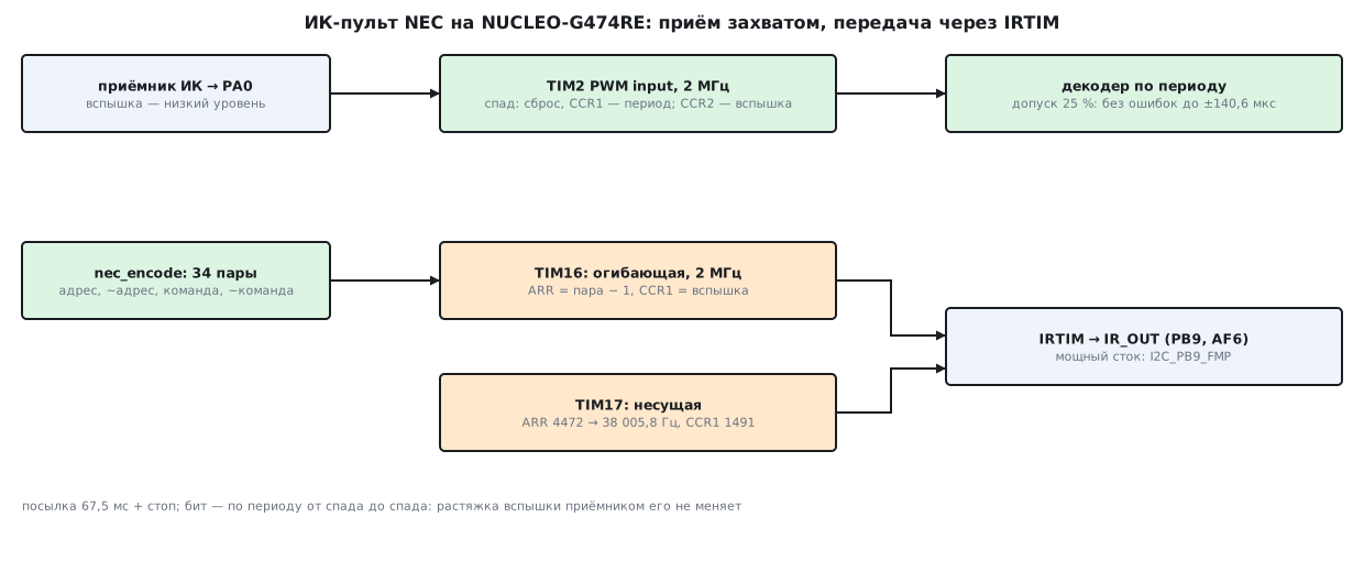
The alternate functions are from the DS12288 table: PA0 is AF1 TIM2_CH1, PB9 is
AF6 IR_OUT. According to RM0440 (chapter 33), PB9 and PA13 are the only pins with
a high-current sink for an LED; it is enabled by the I2C_PB9_FMP bit in
SYSCFG_CFGR1.
198о.2 The NEC protocol
The protocol time unit is 562.5 µs. A message:
| Part | Mark | Space |
|---|---|---|
| leader | 9 ms | 4.5 ms |
| bit 0 | 562.5 µs | 562.5 µs |
| bit 1 | 562.5 µs | 1687.5 µs |
| stop | 562.5 µs | — |
| repeat, while the button is held | 9 ms | 2.25 ms, then a stop mark |
The 32 bits go LSB first: address, inverted address, command, inverted command. The inversions give exactly 16 ones and 16 zeros in any message, so it always has the same length: 34 pairs, 67.5 ms up to the stop mark and 68.0625 ms including it. The inversions also serve as a check: a byte and its complement together give 0xFF.
198о.3 Reception: capture in PWM input mode
The receiver output is low during a mark (that is the case for typical IR receivers;
for yours, check its datasheet). So the start of a mark is a falling edge.
TIM2 is configured as RM0440 describes in 29.4.8: both capture channels
look at the same TI1 input, the first on the falling edge, the second on the rising edge,
and the falling edge also resets the counter (slave reset mode). On
each falling edge CCR1 holds the time since the previous falling edge, the period of the pair,
and CCR2 the length of the previous mark. One interrupt, one ready pair.
void TIM2_IRQHandler(void)
{
    uint32_t total = TIM2->CCR1, mark = TIM2->CCR2;          /* чтение CCR1 сбрасывает CC1IF */
    int e = nec_rx_pair(&rx, mark, total);
    if (e != NEC_NONE)
        last_ev = e;
}
The TIM2 clock is 170 MHz / 85 = exactly 2 MHz, the capture step is 0.5 µs, and all NEC timings are whole numbers of such steps: 562.5 µs = 1125. The leader pair arrives on the falling edge of the first bit, the pair of the last bit on the falling edge of the stop mark, so the message is complete without waiting for the space after it.
There are 34 interrupts per message. Polling the input from a timer at 20 kHz over the same 68.0625 ms takes 1361 interrupts, at 10 kHz 680, and the 50 or 100 µs polling step adds jitter of its own.
198о.4 The decoder and its tolerances
The decoder compares a duration with the nominal value within a tolerance; if the windows
of two nominal values overlap, the nearer one wins. A bit can be determined
in two ways: by the space (a 562.5 µs mark and a 562.5 or 1687.5 µs space)
or by the period from falling edge to falling edge (1125 or 2250 µs). The second is what
CCR1 gives directly.
Experiment: 500 messages each with a random address and command, every edge shifted by a random time within ±J, period-based decoder:
| Tolerance | J = 0 | 50 | 100 | 150 | 200 | 250 | 300 µs |
|---|---|---|---|---|---|---|---|
| 15 % | 500 | 500 | 332 | 14 | 2 | 0 | 0 |
| 25 % | 500 | 500 | 500 | 475 | 126 | 20 | 2 |
| 35 % | 500 | 500 | 500 | 500 | 496 | 246 | 80 |
The period is the difference of two falling edges, so its error is at most 2J. Hence the limit up to which the decoder never makes a single error: the narrowest spot is bit 0 (1125 µs), and the tolerance is also limited by the midpoint to bit 1 (562.5 µs):
| Tolerance | Bit 0 | Bit 1 | Leader | Limit |
|---|---|---|---|---|
| 15 % | 84.4 µs | 168.8 µs | 562.5 µs | 84.4 µs |
| 25 % | 140.6 µs | 281.2 µs | 562.5 µs | 140.6 µs |
| 35 % | 196.9 µs | 281.2 µs | 562.5 µs | 196.9 µs |
The experiment table agrees with it: inside the limit it is 500 out of 500, beyond it messages start to get lost. For bit 1 the window already hits the midpoint at 25 %: beyond that it is limited by the midpoint, not by the tolerance; for bit 0 this happens at 50 %.
Mark stretching. If the receiver lengthens a mark, so that its end lags more than its start, the mark changes, but the period from falling edge to falling edge does not. Experiment: the mark is longer by D, jitter 50 µs, tolerance 25 %:
| Decoder | D = 0 | 100 | 200 | 300 µs |
|---|---|---|---|---|
| by period | 500 | 500 | 500 | 500 |
| by space | 500 | 0 | 0 | 0 |
The period from falling edge to falling edge does not notice the stretching at all. The space-based decoder also checks the mark: 562.5 + 100 µs is already +17.8 %, with jitter it goes beyond 25 % in almost every one of the 32 bits, and the whole message is lost. That is why the device determines the bit by the period and checks the mark only as a sanity check: it is shorter than the period.
198о.5 Transmission: IRTIM, TIM17 and TIM16
According to RM0440 (chapter 33), IRTIM takes the carrier from TIM17_OC1 and the envelope from
TIM16_OC1 and outputs the result on IR_OUT. TIM17 counts at 170 MHz: a period of
4473 clocks (ARR = 4472) gives 38005.8 Hz, 0.0153 % above 38 kHz;
CCR1 = 1491 is a third of the period, 26.31 µs per carrier period, 21.38
periods per 562.5 µs step.
TIM16 counts at 2 MHz and in PWM mode 1 holds the output while the counter
is below CCR1. Each NEC pair is one TIM16 period: ARR = mark +
space − 1, CCR1 = mark:
| Pair | ARR |
CCR1 |
|---|---|---|
| leader | 26999 | 18000 |
| bit 0 | 2249 | 1125 |
| bit 1 | 4499 | 1125 |
| stop | 1124 | 1125 |
The largest value is 26999; it fits into the 16 bits of TIM16. The registers
are preloaded: what is written in the end-of-period interrupt takes effect from the
next period, so the interrupt writes the pair after next. After the stop
mark CCR1 = 0, which means silence, and the timer stops.
The envelope and the carrier count independently, so a mark starts at any point of the carrier period: its length wanders within one period, 26.31 µs. That is several times less than the limits from 198о.4.
198о.6 Firmware and build
ir_g474.c is all CMSIS registers. The clock is HSI16 / 4 × 85 / 2 = 170 MHz,
as in the board's BSP example. Receiver: CCMR1 routes TI1 to both channels,
CCER gives the falling edge to the first and the rising edge to the second, SMCR sets the TI1FP1 trigger and
reset mode. Transmitter: TIM17 and TIM16 in PWM mode 1 with preload, both
with the MOE bit. A level change on PC13 (button B1) sends command
0x08 to address 0x04, and what is received goes as a line to LPUART1.
Build-time checks: 170 MHz / 85 = exactly 2 MHz; the carrier ARR = 4472, its
error is below 0.1 %; CCR1 = 1491; the leader pair fits into 16 bits.
armclang 6.24 built the core and the firmware without warnings: 560 and 914 bytes
of code, 324 bytes of RAM.
198о.7 Pitfalls
Bit by the space. Mark stretching by the receiver eats into the space: at D = 100 µs the space-based decoder lost all 500 messages, the period-based one not a single one.
Tolerance by multiplication. The check difference × 100 <= nominal × tolerance
overflows on huge periods, and after a long silence the 32-bit
timer returns exactly that. The core first compares the difference with the
nominal value, and only then multiplies.
Overlapping windows. The leader (13.5 ms) and the repeat (11.25 ms) at a 25 % tolerance fall into each other's windows. Pick the nearer nominal value.
Without MOE. TIM16 and TIM17 have a break block with a common output
enable: without MOE in BDTR there is nothing on the pin.
UG triggered an interrupt. Writing UG to load the first pair raises
the update flag, and the interrupt shifts the table by one step. URS = 1 leaves
the interrupt only to the end of the period.
A weak pin. An LED on an ordinary pin will not get enough current; a high-current
sink exists only on PB9 and PA13 (I2C_PB9_FMP).
Polling instead of capture. 1361 interrupts per message at 20 kHz versus 34, and the polling step adds to the jitter.
198о.8 Summary
- NEC: a 562.5 µs step, 34 pairs, 67.5 ms up to the stop mark; the inversions of address and command provide a check and a constant length.
- TIM2 capture in PWM input mode:
CCR1is the period,CCR2the mark, 34 interrupts per message versus 1361 when polling at 20 kHz. - The period-based decoder tolerates edge jitter without a single error up to 84.4 / 140.6 / 196.9 µs at a tolerance of 15 / 25 / 35 %; it does not notice mark stretching up to 300 µs, while the space-based decoder breaks already at 100 µs.
- Transmission through IRTIM: the TIM17 carrier is 38005.8 Hz (+0.0153 %),
1/3 duty cycle; the TIM16 envelope runs at 2 MHz,
ARRup to 26999. - The Python model repeated all the experiments bit for bit.
- armclang: 560 + 914 bytes of code, 324 bytes of RAM.
Full source code
ir_g474.c: the NEC IR remote on the NUCLEO-G474RE, reception and transmission.
/* ir_g474.c — раздел 198о: ИК-пульт NEC на NUCLEO-G474RE (STM32G474RE), регистры CMSIS.
 * Такт — HSI16 / 4 × 85 / 2 = 170 МГц, как в примере BSP платы.
 * Приём: выход приёмника (вспышка — низкий уровень) на TIM2_CH1 (PA0, AF1), режим PWM input, такт 2 МГц:
 *   спад — сброс счётчика и захват периода в CCR1, фронт — захват длины вспышки в CCR2.
 * Передача: IRTIM на PB9 (AF6): TIM17 — несущая 38 кГц, скважность 1/3; TIM16 — огибающая по таблице ARR/CCR1,
 *   такт 2 МГц, новое значение — в прерывании по обновлению (предзагрузка: вступит со следующего периода).
 * Изменение уровня на PC13 (кнопка B1) — послать команду; принятое — строкой в LPUART1 (PA2, PA3). */
#include "stm32g4xx.h"
#include "ir_core.h"

#define SYSCLK_HZ   170000000u
#define TICK_HZ     2000000u
#define TICK_PSC    (SYSCLK_HZ / TICK_HZ - 1u)
#define CAR_HZ      38000u
#define CAR_ARR     (SYSCLK_HZ / CAR_HZ - 1u)
#define CAR_CCR     ((CAR_ARR + 1u) / 3u)
#define VCP_BRR     ((uint32_t)(((uint64_t)SYSCLK_HZ * 256u + 57600u) / 115200u))

_Static_assert(SYSCLK_HZ % TICK_HZ == 0u && TICK_PSC == 84u, "170 МГц / 85 = 2 МГц ровно: такт — полмикросекунды");
_Static_assert(CAR_ARR == 4472u, "170 МГц / 38 кГц = 4473,7 → период 4473 такта");
_Static_assert(SYSCLK_HZ / (CAR_ARR + 1u) - CAR_HZ < 38u, "несущая 38 005 Гц — ошибка меньше 0,1 %");
_Static_assert(CAR_CCR == 1491u, "вспышка несущей — треть периода");

static nec_rx rx;
static nec_pair tx[NEC_MAX_PAIRS];
static uint16_t tx_arr[NEC_MAX_PAIRS], tx_ccr[NEC_MAX_PAIRS];
static volatile unsigned tx_n, tx_i;
static volatile int last_ev;

void TIM2_IRQHandler(void)
{
    uint32_t total = TIM2->CCR1, mark = TIM2->CCR2;          /* чтение CCR1 сбрасывает CC1IF */
    int e = nec_rx_pair(&rx, mark, total);
    if (e != NEC_NONE)
        last_ev = e;
}

void TIM1_UP_TIM16_IRQHandler(void)
{
    TIM16->SR = ~TIM_SR_UIF;
    if (++tx_i + 1u < tx_n) {                               /* в предзагрузку — пара через одну */
        TIM16->ARR = tx_arr[tx_i + 1u];
        TIM16->CCR1 = tx_ccr[tx_i + 1u];
    } else if (tx_i + 1u == tx_n) {
        TIM16->CCR1 = 0;                                    /* после стоповой вспышки — тишина */
    } else {
        TIM16->CR1 &= ~TIM_CR1_CEN;
    }
}

static void send(uint8_t addr, uint8_t cmd)
{
    tx_n = nec_encode(addr, cmd, tx);
    nec_timer_values(tx, tx_n, tx_arr, tx_ccr);
    tx_i = 0;
    TIM16->ARR = tx_arr[0];
    TIM16->CCR1 = tx_ccr[0];
    TIM16->EGR = TIM_EGR_UG;                                /* первая пара — сразу в рабочие регистры */
    TIM16->ARR = tx_arr[1];                                 /* вторая — в предзагрузку */
    TIM16->CCR1 = tx_ccr[1];
    TIM16->CR1 |= TIM_CR1_CEN;
}

static void clocks(void)
{
    RCC->APB1ENR1 |= RCC_APB1ENR1_PWREN | RCC_APB1ENR1_TIM2EN;
    PWR->CR5 &= ~PWR_CR5_R1MODE;
    FLASH->ACR = (FLASH->ACR & ~FLASH_ACR_LATENCY) | FLASH_ACR_LATENCY_4WS;
    RCC->PLLCFGR = RCC_PLLCFGR_PLLSRC_HSI | (4u - 1u) << RCC_PLLCFGR_PLLM_Pos | 85u << RCC_PLLCFGR_PLLN_Pos | RCC_PLLCFGR_PLLREN;
    RCC->CR |= RCC_CR_PLLON;
    while (!(RCC->CR & RCC_CR_PLLRDY)) {
    }
    RCC->CFGR = (RCC->CFGR & ~RCC_CFGR_SW) | RCC_CFGR_SW_PLL;
    while ((RCC->CFGR & RCC_CFGR_SWS) != RCC_CFGR_SWS_PLL) {
    }
    RCC->AHB2ENR |= RCC_AHB2ENR_GPIOAEN | RCC_AHB2ENR_GPIOBEN | RCC_AHB2ENR_GPIOCEN;
    RCC->APB2ENR |= RCC_APB2ENR_TIM16EN | RCC_APB2ENR_TIM17EN | RCC_APB2ENR_SYSCFGEN;
    RCC->APB1ENR2 |= RCC_APB1ENR2_LPUART1EN;
}

static void pins(void)
{
    /* PA0 — AF1 (TIM2_CH1), PA2/PA3 — AF12 (LPUART1), PB9 — AF6 (IR_OUT); PC13 — вход кнопки */
    GPIOA->MODER = (GPIOA->MODER & ~(3u << 0 | 0xFu << 4)) | 2u << 0 | 0xAu << 4;
    GPIOA->AFR[0] = (GPIOA->AFR[0] & ~(0xFu << 0 | 0xFFu << 8)) | 1u << 0 | 0xCCu << 8;
    GPIOB->MODER = (GPIOB->MODER & ~(3u << 18)) | 2u << 18;
    GPIOB->AFR[1] = (GPIOB->AFR[1] & ~(0xFu << 4)) | 6u << 4;
    SYSCFG->CFGR1 |= SYSCFG_CFGR1_I2C_PB9_FMP;              /* мощный сток на PB9 — для светодиода (RM0440, 33) */
    GPIOC->MODER &= ~(3u << 26);
}

static void receiver(void)
{
    TIM2->PSC = TICK_PSC;
    TIM2->ARR = 0xFFFFFFFFu;
    TIM2->CCMR1 = TIM_CCMR1_CC1S_0 | TIM_CCMR1_CC2S_1 | 3u << TIM_CCMR1_IC1F_Pos | 3u << TIM_CCMR1_IC2F_Pos;   /* IC1, IC2 — от TI1 */
    TIM2->CCER = TIM_CCER_CC1P | TIM_CCER_CC1E | TIM_CCER_CC2E;   /* IC1 — спад, IC2 — фронт */
    TIM2->SMCR = TIM_SMCR_TS_2 | TIM_SMCR_TS_0 | TIM_SMCR_SMS_2;  /* запуск TI1FP1, режим сброса */
    TIM2->DIER = TIM_DIER_CC1IE;
    TIM2->CR1 = TIM_CR1_CEN;
    nec_rx_init(&rx, 25u, NEC_BY_PERIOD);
    NVIC_EnableIRQ(TIM2_IRQn);
}

static void transmitter(void)
{
    TIM17->PSC = 0;
    TIM17->ARR = CAR_ARR;
    TIM17->CCR1 = CAR_CCR;
    TIM17->CCMR1 = 6u << TIM_CCMR1_OC1M_Pos | TIM_CCMR1_OC1PE;    /* ШИМ, режим 1 */
    TIM17->CCER = TIM_CCER_CC1E;
    TIM17->BDTR = TIM_BDTR_MOE;                             /* у TIM16/TIM17 есть блок защиты: без MOE выхода нет */
    TIM17->CR1 = TIM_CR1_CEN;
    TIM16->PSC = TICK_PSC;
    TIM16->CCMR1 = 6u << TIM_CCMR1_OC1M_Pos | TIM_CCMR1_OC1PE;
    TIM16->CCER = TIM_CCER_CC1E;
    TIM16->BDTR = TIM_BDTR_MOE;
    TIM16->CR1 = TIM_CR1_ARPE | TIM_CR1_URS;                /* UG не поднимает UIF: прерывание — только по концу периода */
    TIM16->DIER = TIM_DIER_UIE;
    NVIC_EnableIRQ(TIM1_UP_TIM16_IRQn);
}

static void vcp_put(const char *s)
{
    while (*s) {
        while (!(LPUART1->ISR & USART_ISR_TXE))
            ;
        LPUART1->TDR = (uint8_t)*s++;
    }
}

int main(void)
{
    static const char hex[] = "0123456789ABCDEF";
    clocks();
    pins();
    LPUART1->BRR = VCP_BRR;
    LPUART1->CR1 = USART_CR1_TE | USART_CR1_UE;
    receiver();
    transmitter();
    uint32_t was = 0;
    for (;;) {
        uint32_t b = GPIOC->IDR & (1u << 13);
        if (b != was && !(TIM16->CR1 & TIM_CR1_CEN))
            send(0x04, 0x08);
        was = b;
        int e = last_ev;
        if (e == NEC_FRAME || e == NEC_REPEAT) {
            last_ev = NEC_NONE;
            char s[] = "NEC a=00 c=00 r\r\n";
            s[6] = hex[rx.addr >> 4]; s[7] = hex[rx.addr & 15u];
            s[11] = hex[rx.cmd >> 4]; s[12] = hex[rx.cmd & 15u];
            s[14] = e == NEC_REPEAT ? 'R' : ' ';
            vcp_put(s);
        }
    }
}
Next: section 198п "Mini-project: MIDI — a UART input at 31250 and a synthesizer on the DAC".