 Embedded HandbookApps
197. Mini-project: a frequency counter on a timer
The second device is a frequency counter: a square-wave signal goes to the PA0 input, and twice a second the frequency is printed to the console. The task looks simple, but it contains two classic traps: which measurement method to choose for which frequency, and how not to be off by 65536 clock ticks when the 16-bit timer overflows at the very moment an edge arrives.
Like the thermostat (section 196), the device is split into logic (freq.c) and
platform (plat_f103.c); the logic was run on a computer for frequencies
from 1 Hz to 10 MHz, and the firmware was built for the BluePill. The files are in _verify/proj197/,
checked by _verify/proj197_check.py.
Terms used in the documentation
Term Meaning input capture capture: the timer stores its count on an input edge gated counting counting pulses during a "gate" time reciprocal counting measuring through the period, with averaging update event (overflow), UIF the timer overflow and its flag quantization error, ±1 count the quantization error, "±1 count" external clock mode, ETR clocking the timer externally from an input
197.1 Three ways to measure frequency
| Method | How | Error (±1 count) | Good for |
|---|---|---|---|
| from a single period | capture two adjacent edges; f = fclk / (t₁ − t₀) | ≈ f / fclk | low frequencies |
| by counting | pulses in 1 s | ≈ 1 / (f · 1 s) | high frequencies |
| averaging periods | the first and last edge within a second, n periods between them | ≈ 1 / (fclk · 1 s) | all of them — if you can keep counting periods |
The errors of the first two go in opposite directions: one grows with frequency, the other falls. They are equal when f / fclk = 1 / (f · T), that is, at
f = √(fclk / T) = √(72 MHz / 1 s) ≈ 8485 Hz.
Below that it pays to measure the period, above it to count pulses. The function
freq_prefer_period chooses the method by the same formula.
197.2 A run: the error from 1 Hz to 10 MHz
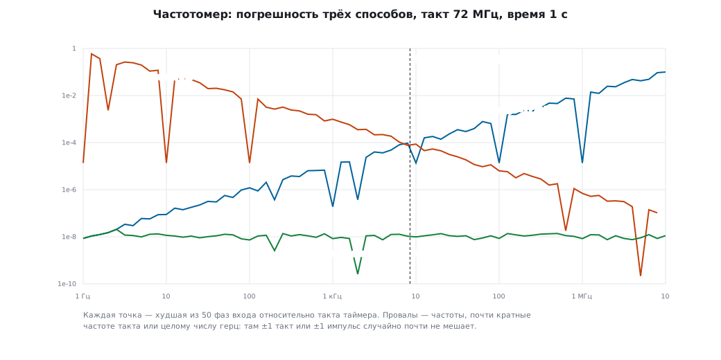
For each frequency, the model on the computer tries 50 different phases of the input relative to the timer clock and takes the worst error:
| Frequency | From a single period | Counting for 1 s | Averaging over 1 s | Chosen |
|---|---|---|---|---|
| 10 Hz | 7.0·10⁻⁸ | 9.9·10⁻² | 8.4·10⁻⁹ | period |
| 1 kHz | 1.2·10⁻⁵ | 8.6·10⁻⁴ | 1.1·10⁻⁸ | period |
| 8485 Hz | 6.8·10⁻⁵ | 1.0·10⁻⁴ | 1.3·10⁻⁸ | period |
| 100 kHz | 1.3·10⁻³ | 7.0·10⁻⁶ | 1.2·10⁻⁸ | counting |
| 1 MHz | 1.4·10⁻² | 7.0·10⁻⁷ | 8.3·10⁻⁹ | counting |
- Counting at 10 Hz is off by 10 %: there are 10 pulses in a second, and ±1 is a tenth.
- One period at 1 MHz is 72 clock ticks, and ±1 tick is 1.4 %.
- Around 8.5 kHz both methods give about 10⁻⁴ — the crossover point is where it should be. The 8485 Hz row lies slightly below the boundary √(72·10⁶) ≈ 8485.3 Hz, so the period is chosen; at the boundary itself the error estimates are equal, and the choice does not matter.
- Averaging gives about 10⁻⁸ at all frequencies: ±1 tick over a whole second.
So why not always measure by averaging? You need to know the number of periods
between the first and the last capture. At low frequencies the program counts it
in the capture interrupt; at megahertz frequencies an interrupt on every edge can no longer keep up —
the periods are counted by a second timer. The PA0 input belongs only to TIM2 (both TIM2_CH1
and TIM2_ETR), so the same signal is also wired to an input of another timer,
for example to TIM3_CH1 (PA6) in external clock mode.
197.3 The trap: capture and overflow at the same moment
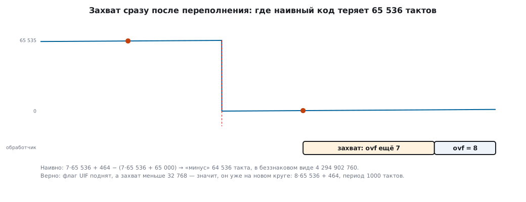
The timer is 16-bit, and at 72 MHz it overflows 1099 times a second. That is the F103 case: on the F4, F7, G4, L4 and H7, the TIM2 and TIM5 timers are 32-bit, at 72 MHz they overflow once every 59.7 s, and for periods shorter than that no extension is needed. The capture time is extended to 32 bits: the upper bits are an overflow counter, incremented by the overflow interrupt. The dangerous moment is when an edge arrives right after an overflow, and the overflow interrupt has not been handled yet: the capture is already small (a "new lap"), but the overflow counter is still the old one.
The check in the model: the true period is 1000 ticks, the first capture is at 65000 with 7 overflows, the second at 464, already after the overflow:
| Code | Period | Frequency |
|---|---|---|
naive: ovf << 16 \| capture |
4294902760 ticks | 0.017 Hz |
| fixed | 1000 ticks | 72000.0 Hz |
The fix is to look at the overflow flag at the moment of capture:
uint32_t hi = ovf;
if (uif_pending && capture < 0x8000u)
    hi++;
return hi << 16 | capture;
If the flag is pending and the capture is small (less than half a lap), the edge arrived after the overflow — one is added to the upper part. If the capture is large (65500), the edge came before the overflow, and nothing may be added: the model checked this case as well.
197.4 Firmware for the BluePill
plat_f103.c:
- clock: an 8 MHz crystal × 9 = 72 MHz; APB1 = 36 MHz, but the timers on APB1 with a prescaler of 2 get double the frequency — 72 MHz;
- the PA0 input is TIM2_CH1 (and ETR); capture on the rising edge, filter of 8 clock ticks: it passes a level that lasts at least 8 / 72 MHz = 111 ns — for a square wave that is up to 4.5 MHz;
- in the TIM2 interrupt the capture is handled first (with a check of the overflow flag), and then the overflow itself;
- every 500 ms: if there are two or more captures, the average over them, if one, from
the last period; the result is formatted by
freq_formatand sent to USART1 (divider 625: 72 MHz / 625 = exactly 115200 baud).
⚠️ PA0 on the F103 is not 5 V tolerant: it has an ADC input and no FT marking (appendix E). A signal from 5-volt logic or from a generator is fed through a divider (section 62.4) or through a signal conditioner (197.5).
Built with arm-none-eabi-gcc -Os for Cortex-M3: 3744 bytes of Flash, 28 bytes of RAM.
A noticeable part is software double arithmetic (the Cortex-M3 has no FPU): double-precision
addition and multiplication take about 600 bytes each.
The limit of the firmware itself is the interrupt on every edge. The capture path in
TIM2_IRQHandler is 35 instructions, and with interrupt entry (12 cycles plus
Flash wait states, section 7), exit, and accesses to the timer on APB1,
that is roughly a hundred cycles per edge — an estimate from the disassembly, not a measurement.
So the firmware keeps up to about 72 MHz / 100 ≈ 700 kHz, and with a margin
for the rest of the program, half that; above it, it "hangs" (197.6). A cheap way
to extend the range is the capture prescaler — the IC1PSC field in
CCMR1: capture every 2nd, 4th or 8th edge, with that many times fewer
interrupts, and the measured period is divided by 2, 4 or 8. Higher still —
hardware counting (197.5).
Output format: five significant digits and a prefix: 1234.5678 Hz → "1.2346 kHz"; 999999 Hz after rounding is "1.0000 MHz", not "1000.00 kHz".
197.5 What to improve
- Counting at high frequencies: TIM2 is switched to external clocking from ETR
(the same PA0 pin, mode 2, the
ECEbit), and it counts the pulses itself, while the 1 s gate is timed by TIM3 through the internal trigger line: for TIM2 that isITR2, slave mode "gated". Above about 8.5 kHz this is more accurate. Without a prescaler, ETR accepts up to a quarter of the timer clock — 18 MHz. - Integer arithmetic instead of
double: the frequency in millihertz in a 64-bit integer — a kilobyte less code. - A divider at the input (74HC4040 and similar) — for frequencies above tens of megahertz.
- An input conditioner (a comparator with hysteresis, section 44) — for sine waves and noisy signals.
197.6 Pitfalls
The frequency "jumps" by orders of magnitude once a minute. The capture and overflow race: the naive extension is off by exactly 65536 ticks.
At 10 Hz it shows 9, then 10, then 11. Counting over a second: ±1 pulse is 10 %. For low frequencies, use the period.
At 1 MHz the error is several percent. One period is 72 ticks. Above 8.5 kHz, use counting or averaging.
The frequency is twice the real one. Capture on both edges instead of one.
A timer on APB1 ticks at the wrong frequency. When the APB1 prescaler is not 1, the timer gets double the bus frequency — 72 MHz, not 36.
At high frequencies the device "hangs". An interrupt on every edge: at a megahertz the processor has no time for anything else. There, use hardware counting.
197.7 Summary
- From the period the error is ≈ f / fclk, by counting ≈ 1 / (f · T); they are equal at √(fclk / T) ≈ 8485 Hz.
- The model: 10 Hz by counting — 10 % error, 1 MHz from a single period — 1.4 %; averaging over a second — about 10⁻⁸ everywhere.
- Capture and overflow: look at the overflow flag at the moment of capture, otherwise the error is exactly 65536 ticks.
- The BluePill firmware is 3744 bytes; the TIM2 timer runs at 72 MHz with APB1 = 36 MHz.
Full sources
freq.c — the frequency counter logic without hardware.
/* Мини-проект «Частотомер»: логика без железа.
 *
 * Два способа. По периоду: таймер считает такты f_clk, захват по фронту входа; частота = f_clk × N / (tN − t0).
 * Счётом: вход тактирует счётчик, за ворота T считаем импульсы; частота = импульсы / T.
 * Погрешность ±1 такта у первого — f/f_clk от периода; ±1 импульса у второго — 1/(f·T). Выбирается тот,
 * у которого она меньше; равны они при f = √(f_clk / T).
 *
 * Таймер 16-битный: к захвату дописываются старшие биты из счётчика переполнений. Если переполнение
 * и захват случились почти одновременно, наивный код ошибается ровно на 65 536 тактов — см. extend(). */
#include <stdint.h>

#include "freq.h"

/* Расширение 16-битного захвата до 32 бит.
 * ovf — счётчик переполнений, прочитанный в обработчике захвата; uif — флаг переполнения, ещё не
 * обработанный в этот момент (переполнение пришло, но его прерывание ждёт). Если захват маленький
 * (< половины периода), а переполнение висит, — захват случился ПОСЛЕ переполнения: +1 к старшей части. */
uint32_t freq_extend(uint16_t capture, uint16_t ovf, int uif_pending)
{
    uint32_t hi = ovf;
    if (uif_pending && capture < 0x8000u)
        hi++;
    return hi << 16 | capture;
}

uint32_t freq_extend_naive(uint16_t capture, uint16_t ovf, int uif_pending)
{
    (void)uif_pending;
    return (uint32_t)ovf << 16 | capture;
}

/* по периоду: t0 и tn — расширенные захваты, n периодов между ними */
double freq_by_period(uint32_t t0, uint32_t tn, uint32_t n, double f_clk)
{
    uint32_t dt = tn - t0;                    /* разность беззнаковых — верна и через переполнение 32 бит */
    return dt ? f_clk * n / dt : 0.0;
}

double freq_by_count(uint32_t pulses, double gate_s)
{
    return pulses / gate_s;
}

/* какой способ точнее: сравнить относительные погрешности ±1 такт и ±1 импульс */
int freq_prefer_period(double f_est, double f_clk, double gate_s)
{
    return f_est / f_clk < 1.0 / (f_est * gate_s);
}

/* «12.345 кГц»: 5 значащих цифр, приставка по величине */
void freq_format(double f, char *out, int n)
{
    static const char *const unit[] = {"Гц", "кГц", "МГц"};
    int u = 0;
    while (f >= 1000.0 && u < 2) {
        f /= 1000.0;
        u++;
    }
    /* после округления до пяти цифр 999,999 превращается в 1000,00 — тогда на ступень выше */
    if (f >= 999.995 && u < 2) {
        f /= 1000.0;
        u++;
    }
    int dec = f >= 99.9995 ? 2 : f >= 9.99995 ? 3 : 4;
    long scaled = (long)(f * (dec == 2 ? 100 : dec == 3 ? 1000 : 10000) + 0.5);
    long ip = scaled / (dec == 2 ? 100 : dec == 3 ? 1000 : 10000);
    long fp = scaled % (dec == 2 ? 100 : dec == 3 ? 1000 : 10000);
    /* ручная печать без printf: целая часть, точка, дробная с ведущими нулями */
    char b[24];
    int i = 0;
    char t[12];
    int k = 0;
    do {
        t[k++] = (char)('0' + ip % 10);
        ip /= 10;
    } while (ip);
    while (k)
        b[i++] = t[--k];
    b[i++] = '.';
    for (long d = (dec == 2 ? 10 : dec == 3 ? 100 : 1000); d; d /= 10)
        b[i++] = (char)('0' + (fp / d) % 10);
    b[i++] = ' ';
    for (const char *s = unit[u]; *s && i < 23; s++)
        b[i++] = *s;
    b[i] = 0;
    for (k = 0; k < n - 1 && b[k]; k++)
        out[k] = b[k];
    out[k] = 0;
}
Next: section 198 "Mini-project: an RTC clock with an alarm and rate correction".