 Embedded HandbookApps
198а. Mini-project: a battery-powered sensor — a year on one CR2032
The thermostat from section 196 and the clock from section 198 run from a wall socket. The fourth device is a logging thermometer that lives for a year on a single CR2032 coin cell: once a minute it wakes up on an RTC alarm, measures the temperature, adds to a log in Flash and goes back to sleep. All of section 10 turns here from theory into a line of expenses: every microamp is days of the device's life.
The heart of the project is not the code but the energy budget: work out the average current before you solder, and know which line of the budget dominates. Spoiler: not the bursts of work, but the sleep current — and the leakage you cannot see on the schematic.
Project files are in _verify/batt198a/: batt.h, batt.c (logic and the ring
log), plat_f103.c (the BluePill platform), sim_host.c (a model of the Flash
and the sensor for the computer), budget.py (the budget with a dimension check).
The firmware is built for Cortex-M3, and a full year of operation has been run on the computer.
Checked by _verify/batt198a_check.py.
Terms used in the documentation
Term Meaning coin cell, button cell a flat disc-shaped battery nominal capacity (mA·h) rated capacity, in milliamp-hours continuous drain, standard load steady discharge current, the reference load pulse drain discharge in current pulses end (cut-off) voltage the voltage at which discharge is considered complete internal resistance the source's own series resistance shelf life how long the cell keeps in storage battery life how long the device runs on one battery
198а.1 What the device does
| Function | How |
|---|---|
| wake up once a minute | RTC alarm from a 32768 Hz crystal (section 198.5), EXTI 17 event |
| measure temperature | 10 kΩ NTC in a divider, a 17-point table — as in section 196.3 |
| not feed the divider for nothing | the upper leg is powered from pin PA2 only during the measurement |
| remember a year | log in Flash: a ring of 8 pages, one record every 10 minutes |
| know the battery state | supply voltage via the internal reference VREFINT, written to the log |
| hand over the log | a button on PA0 wakes the chip, the log goes out over USART1 at 115200 baud |
| sleep the rest of the time | Stop, regulator in low-power mode, ≈15.4 µA together with the RTC |
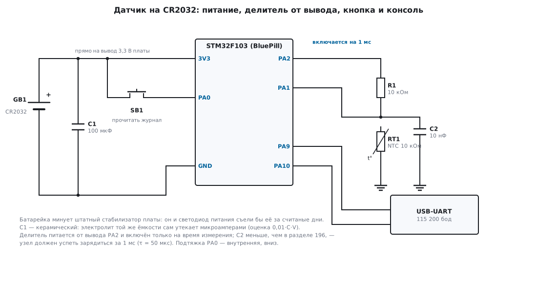
The battery is connected directly to the board's 3.3 V rail, bypassing the on-board regulator: the regulator and the power LED would eat it in a matter of days (198а.7). The F103 operating range is 2.0…3.6 V, so a CR2032 fits without any converters: a fresh one gives about 3 V, and the end-of-discharge voltage of a coin cell is exactly 2.0 V.
⚠️ The ADC only down to 2.4 V. The chip may be powered down to 2.0 V, but the analog supply with the ADC running is specified from 2.4 V. Below that the device still lives and writes the log, but measurement accuracy is no longer guaranteed. The divider, however, measures correctly for longer than you might think: it is powered from the same voltage as the ADC reference, and the code does not depend on the sagging supply (ratiometric measurement, section 96.2).
198а.2 Budget: calculate first, then solder
The capacity of a CR2032 from well-known manufacturers is typically 220–235 mA·h; the calculation uses a conservative 220. An honest caveat: those milliamp-hours are promised for discharge at a "steady" current of about 0.2 mA (standard load 15 kΩ) down to 2.0 V at room temperature. Milliamp pulses are hard on the battery: the internal resistance of a fresh cell is tens of ohms, near the end of discharge it is hundreds, and a current burst pulls the voltage down.
⚠️ The burst is supplied by the capacitor, not the battery. A 100 µF ceramic at the supply pin: a 4 mA × 5 ms burst takes a 0.2 V droop from it (ΔU = I·t/C), and the battery delivers the same charge smoothly, at an average current. Without the capacitor the same burst on a drained battery with hundreds of ohms inside drops the supply below reset — the device will "die" on every measurement.
All the chip's currents are taken not from thin air but from the STM32F103x8/B datasheet — the "Supply current characteristics" tables (typical values at 25 °C):
| Mode | Current | Note |
|---|---|---|
| Run, HSI 8 MHz | 4.0 mA | peripherals off |
| Sleep, HSI 8 MHz | 0.6 mA | peripherals off |
| Stop, main regulator | 24 µA | wakeup 3.6 µs |
| Stop, low-power regulator | 14 µA | 13.5 µA at 2.4 V; wakeup 5.4 µs; up to 180 µA at 85 °C |
| Standby | 2 µA | RAM and registers are lost, wakeup 50 µs via reset |
| LSE crystal + RTC | 1.4 µA | 1.1 µA at 2.4 V |
| ADC on (ADON = 1) | +0.8 mA | analog part |
The sleep mode is chosen as in section 10.1. Standby is four times more economical than Stop, but loses RAM: the accumulator of ten one-minute measurements and the ring tail would have to be hidden in the backup registers, and the program would start from scratch every time. For the first version we take Stop with the low-power regulator: 14 µA + 1.4 µA for the RTC with its crystal = 15.4 µA — RAM stays intact, and execution continues from the same line. The Standby gain is worked out in 198а.8.
198а.3 The cycle: wake up → measure → write → sleep
The clock is HSI 8 MHz without the PLL, as in section 196. This is not only about
simplicity: after exiting Stop the system ends up on HSI anyway
(the main pitfall of section 10.3) — and we never left it, so there is nothing
to restore. Sleep is entered without interrupt handlers: the alarm and the button are
set up as EXTI events, and the core is woken by a pair of __WFE:
static void enter_stop(void)
{
    EXTI->RTSR |= (1u << 17) | (1u << 0);
    EXTI->EMR |= (1u << 17) | (1u << 0);               /* события: обработчики прерываний не нужны */
    PWR->CR = (PWR->CR & ~PWR_CR_PDDS) | PWR_CR_LPDS | PWR_CR_CWUF;
    SCB->SCR |= SCB_SCR_SLEEPDEEP_Msk;
    __SEV();
    __WFE();                                           /* снять взведённый флажок события */
    __WFE();                                           /* уснуть по-настоящему */
    SCB->SCR &= ~SCB_SCR_SLEEPDEEP_Msk;
    /* система снова на HSI 8 МГц — мы с него и не уходили */
}
The main loop asks three questions after every wakeup:
    for (;;) {
        if (RTC->CRL & RTC_CRL_ALRF) {                 /* будильник: минутное измерение */
            RTC->CRL &= (uint16_t)~RTC_CRL_ALRF;
            uint32_t now = rtc_now();
            adc_on();
            batt_minute(&b, now);
            adc_off();
            rtc_write(&RTC->ALRH, &RTC->ALRL, now + BATT_PERIOD_S);
        }
        if (GPIOA->IDR & 1u) {                         /* кнопка: журнал в консоль */
            batt_dump(&b);
            while (GPIOA->IDR & 1u) {
            }
        }
        enter_stop();                                  /* ложное пробуждение безвредно: уснём снова */
    }
The measurement is as in 196, with one difference: the divider is powered from pin PA2 and switched on only for the duration of the measurement, otherwise its 150 µA would drain the battery ten times faster than the sleep itself:
    GPIOA->BSRR = GPIO_BSRR_BS2;                       /* подать питание на делитель */
    delay_ms(1);                                       /* установление: τ = 50 мкс при C = 10 нФ */
    uint32_t sum = 0;
    for (int i = 0; i < 16; i++)
        sum += adc_once(1);
    GPIOA->BSRR = GPIO_BSRR_BR2;                       /* снять питание: делитель не ест в сне */
The capacitor at the ADC input is reduced from 100 nF (section 196) to 10 nF: the node must charge within a millisecond of pause, and the noise is taken care of by averaging 16 samples. The pin's output switch holds 0.4 V at 8 mA according to the datasheet — less than 50 Ω; at the divider current that is 7.5 mV, a fraction of a percent of full scale.
Now the arithmetic of a burst. Its typical length is about 2.6 ms: Stop wakeup 5.4 µs, a millisecond for the divider, 20 ADC samples of 63 µs each (1.26 ms), and now and then a log write. The budget allows 5 ms — a twofold margin for future code. The charge of one burst:
q = 4 мА · 5 мс + 0,8 мА · 1,26 мс ≈ 20 + 1 ≈ 21 мкКл
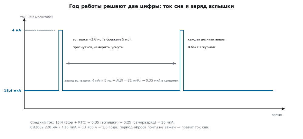
The average current when polling once a minute is the formula from section 10.8 plus two lines that people forget: erasing a log page (5 mA for up to 40 ms — but once per 128 records, 0.003 µA on average) and the self-discharge of the battery itself (around a percent a year — another 0.25 µA):
I_ср = 15,4 + 21 / 60 + 0,25 ≈ 16,0 мкА → 220 000 мкА·ч / 16,0 ≈ 13 700 ч ≈ 1,6 года
A year with a margin of one and a half times. And the main conclusion of the budget: the polling period hardly matters:
| Polling | Average current | Battery life |
|---|---|---|
| every 10 s | 17.8 µA | 1.41 years |
| every 60 s | 16.0 µA | 1.57 years |
| every 10 min | 15.7 µA | 1.60 years |
The bursts account for only 0.35 µA out of 16 — two percent of consumption. This is the mirror image of the example from section 10.8, where the burst ate 72 %: there the device slept at 20 µA but woke up every second. In our device the sleep current rules — and that is why the hunt in 198а.7 is aimed at leakage.
198а.4 The log in Flash: a ring with round-robin wear
A record is 8 bytes, with no alignment holes; times are the RTC seconds counter (section 198.2):
struct batt_rec {                                      /* 8 байт во Flash, без выравнивающих дыр */
    uint32_t t;                                        /* время RTC, секунды; 0xFFFFFFFF — пусто */
    int16_t  t_c10;                                    /* температура, десятые доли °C, среднее за 10 минут */
    uint8_t  vbat;                                     /* (напряжение в мВ − 1000) / 10: 1,00…3,55 В */
    uint8_t  crc;                                      /* CRC-8, полином 0x07, по первым 7 байтам */
};
The one-minute measurements accumulate in RAM, and once every 10 minutes the average goes to the log. The last 8 pages of Flash are given to the log (0x0800E000; the linker script leaves the firmware 56 KB) — 8 × 128 = 1024 records, a history of 6.2–7.1 days: the page being written is erased entirely, so the tail of the history "breathes". The ring is the same record log as for the settings in section 11.8, only in whole pages:
    uint32_t page = b->rec_idx / LOG_RECS_PAGE;
    uint32_t off = b->rec_idx % LOG_RECS_PAGE * LOG_REC_BYTES;
    if (off == 0u)
        plat_log_erase(page);                          /* вошли в страницу — стереть её целиком */
    plat_log_write(page, off, &r, sizeof r);
    b->rec_idx = (b->rec_idx + 1u) % LOG_RECS;
Erasing and writing in half-words is the recipe from section 11.5; where to put calibration coefficients, if they appear, is section 202.5. After a reset the ring tail is searched for again: the newest valid record is the one with the largest time, and if the next cell is occupied by the garbage of an interrupted write, the tail steps further: in Flash you cannot write over what is not erased.
Round-robin wear is back-of-the-envelope arithmetic, confirmed by a run: in a year 52560 records — 411 erases over all 8 pages, no more than 52 per page. The F103 Flash endurance is 10000 cycles: the log wears it by half a percent a year, enough for roughly 190 years. Data retention is promised by the datasheet for 30 years — it will outlive both the battery and the device.
198а.5 Reading the log: a button and the console
The UART receiver is deaf in Stop: there is no clock, and a start bit wakes nobody (later series fix this with the LPUART; the F103 does not have one). So the log is collected with a button: PA0 to the supply plus, internal pull-down (30…50 kΩ per the datasheet), the rising edge is EXTI event 0. Current through the pull-down flows only while the button is pressed.
The device knows no calendar — the log holds bare seconds of its own counter:
t=31950940 T=24.8 U=2.60
The binding to real time is done by the program on the computer at the moment of the dump: real record time = now − (current t − record t). The full ring, 1024 lines, goes out in 2.3 s — that is 9.2 mC, the price of ten minutes of sleep: press the button every day if you like.
🔧 Battery voltage — without a divider. An external divider for measuring the supply would itself become a leak. Instead, the ADC measures the internal reference VREFINT ≈ 1.20 V relative to the supply: U = 1200 · 4096 / code, mV. The reference spread of 1.16…1.24 V gives an error of up to ±0.1 V at 3 V — for the question "is it time to change the battery" that is more than enough. In a log record the voltage takes one byte: a scale of 1.00…3.55 V in 10 mV steps.
198а.6 Running on the computer and building
QEMU does not model Stop mode or currents — this device cannot be verified on it.
So the section stands on two supports: the numbers come from the datasheet in the pack,
the logic uses the same "logic + platform" pair as in 196–198: batt.c
knows nothing about registers and builds on the computer with a model of the Flash
(erase to 0xFF, write only over erased cells, an erase counter
per page) and of the sensor (a daily sine wave with noise, the battery runs down
from 3.05 to 2.60 V over the year).
| What | Result |
|---|---|
| wakeups per year | 525600, log records — 52560 |
| page erases | 411, per page 51…52 — the wear is even |
| ring at the end of the year | 976 records, 585000 s of history (6.8 days), time gaps — 0 |
| tail after a reset | found where it was |
| power loss in the middle of a write | the half record is discarded by CRC, the tail steps past it, the dump is intact |
CRC-8 of 123456789 |
0xF4 — the check value of the implementation |
| dump after a year | 976 lines, the first is t=31950940 T=24.8 U=2.60 |
The firmware is built with arm-none-eabi-gcc -Os for Cortex-M3 without warnings:
| What | Bytes |
|---|---|
| whole firmware (Flash) | 1852 |
| RAM (variables) | 16 |
of which the batt.c logic — code |
632 |
16 bytes of RAM is one struct batt: the log lives in Flash, the buffers
on the stack. Record packing was verified on the computer honestly: both x86-64
and Cortex-M are little-endian, and the structure has no fields with holes, so
the bytes in the model's "Flash" and in the board's Flash are the same.
198а.7 What eats the battery unnoticed
Each line comes from the budget.py budget; the method of finding such leaks
with a multimeter is in section 10.8.
| What was forgotten | Extra current | The battery lasts |
|---|---|---|
| a 40 kΩ pull-up on a pin held to ground | 75 µA | 101 days |
| NTC divider powered from the rail, not from PA2 | 150 µA | 55 days |
| "I'll blink the LED once a minute" — and it stayed on | 1 mA | 9 days |
| debugger: DBG_* bits left over after debugging | ≈0.6 mA | 15 days |
| a 100 µF electrolytic instead of ceramic | ≈3 µA | 482 days |
Notes on the lines:
- Pull-up. 30…50 kΩ inside the chip: 3 V / 40 kΩ = 75 µA — five times more than the entire sleep current. Unused pins go to analog mode (recipe in 10.8); our PA0 pull-down costs nothing while the button is released.
- LED. Even a modest one: (3 V − 2 V) / 1 kΩ = 1 mA. On a battery-powered device an indicator either flashes for milliseconds or does not exist.
- Debugger. With the
DBG_STOP/DBG_STANDBYbits the chip keeps its clocks running in "Stop" — a current of the order of Sleep, 0.6 mA. The bits survive the reset button; only removing power clears them (section 10.8). - The board's on-board regulator and its power LED draw milliamps on their own: the battery is connected bypassing them.
- Capacitors. For an aluminium electrolytic the leakage current is estimated as 0.01·C·U — for 100 µF at 3 V that is 3 µA, minus a quarter of the battery life. X7R ceramic leaks orders of magnitude less.
198а.8 What to improve
- Standby instead of Stop (section 10.4): base 2 + 1.4 = 3.4 µA, average
current 4.0 µA — 6.3 years. The price: the accumulator and the ring tail go into the BKP backup
registers, every wakeup goes through a reset and
Reset_Handler, debugging is less convenient. This is how devices "for the whole life of the battery" are made. - Do not erase a page when the battery is low: the device's own voltage measurement is in every record — below 2.2 V postpone the erase; the log will freeze, but the device will survive until the battery is replaced. The PVD detector (section 10.7) does the same without polling.
- Clock-rate correction (section 198.4): a ±20 ppm crystal drifts the time by 1.7 s a day; for a log over a year that is about ten minutes.
- Sensor calibration at one point (sections 202.3 and 202.5) — the NTC table from 196.3 is shared, but individual thermistors differ.
- A digital sensor DS18B20 (section 96.4) instead of the divider: more accurate and without analog caveats, but 750 ms of conversion — the burst budget has to be recalculated.
198а.9 Pitfalls
The device lives two weeks instead of a year and a half. After debugging,
DBG_* bits were left in DBGMCU->CR: the chip keeps being clocked in "Stop",
the current is 0.6 mA instead of 15 µA. Even the reset button does not clear them — only
cycling the power (section 10.8).
Sleep current is 90 µA, although everything is off in the program. One forgotten pull-up on a pin held low costs 75 µA. Unused pins go to analog mode, and to measure honestly use the method of 10.8: the multimeter in the chip's supply line, not the whole board's.
The device does not answer UART commands. In Stop the receiver is deaf: there is no clock, and a start bit is not a wakeup source (section 10.6). Wake it with a button, as here, or take a chip with an LPUART that can wake up on a start bit.
Near the end of the battery the device reboots — once a day, then more often. This is the log page erase: up to 5 mA for tens of milliseconds. On the internal resistance of a drained coin cell — hundreds of ohms — such a current drops a volt: 5 mA × 200 Ω = 1.0 V, and the supply dives below the reset threshold. Use a larger capacitor, and erase only while the voltage is healthy.
The temperature reads consistently low by a degree or two. The capacitor at the ADC input is larger than calculated: the divider node does not have time to charge during the pause after PA2 is switched on. With 10 nF the time constant is 50 µs and a millisecond is enough; with the 100 nF from section 196 it is not. Either wait longer or use a smaller capacitance.
After a battery change the log is intact, but the time starts from zero. That is by design: the log is in Flash, while the RTC counter ran from the same battery and was reset together with it. The binding to the calendar is done on the computer anyway at the moment of the dump — the next read simply starts a new epoch.
198а.10 Summary
- A year on a CR2032 is a budget, not a feat: sleep 15.4 µA (Stop 14 + RTC 1.4), a 21 µC burst once a minute, self-discharge 0.25 µA — average current 16.0 µA, 220 mA·h lasts ≈13700 h — 1.6 years.
- The sleep current rules: polling every 10 s or every 10 min moves the battery life only between 1.41 and 1.60 years — the bursts are two percent of consumption.
- Log: 8 pages × 128 records of 8 bytes, a history of 6.2–7.1 days; in a year — 52560 records and no more than 52 erases per page — 0.5 % of the 10000-cycle endurance.
- A year run on the computer: 525600 wakeups, 0 time gaps in the ring, an interrupted record discarded by CRC-8 (check value 0xF4).
- Firmware — 1852 bytes of Flash and 16 bytes of RAM; the register-free logic is 632 bytes.
- Leaks are scarier than work: one pull-up (75 µA) turns 1.6 years into 101 days, an LED into 9 days.
Full source code
batt.h — the interface of the device logic and the platform functions.
/* Мини-проект «Датчик на батарейке»: логика прибора без железа.
 * Измерение, накопление и кольцевой журнал во Flash не знают про регистры:
 * всё железное — в функциях платформы (plat_*), которые на BluePill написаны
 * поверх регистров, а на компьютере — поверх модели Flash и термометра. */
#ifndef BATT_H
#define BATT_H

#include <stdint.h>

#define LOG_PAGES      8u                              /* журнал: 8 страниц по 1 КБ в конце Flash */
#define LOG_PAGE_BYTES 1024u
#define LOG_REC_BYTES  8u
#define LOG_RECS_PAGE  (LOG_PAGE_BYTES / LOG_REC_BYTES)   /* 128 записей на страницу */
#define LOG_RECS       (LOG_PAGES * LOG_RECS_PAGE)        /* 1024 записи в кольце */

#define BATT_PERIOD_S  60u                             /* будильник RTC: раз в минуту */
#define BATT_PER_REC   10u                             /* запись в журнал: раз в 10 измерений */

#define REC_EMPTY_T    0xFFFFFFFFu                     /* время в стёртой ячейке */

struct batt_rec {                                      /* 8 байт во Flash, без выравнивающих дыр */
    uint32_t t;                                        /* время RTC, секунды; 0xFFFFFFFF — пусто */
    int16_t  t_c10;                                    /* температура, десятые доли °C, среднее за 10 минут */
    uint8_t  vbat;                                     /* (напряжение в мВ − 1000) / 10: 1,00…3,55 В */
    uint8_t  crc;                                      /* CRC-8, полином 0x07, по первым 7 байтам */
};

struct batt {
    uint32_t rec_idx;                                  /* куда ляжет следующая запись, 0…LOG_RECS−1 */
    uint32_t n_acc;                                    /* сколько поминутных измерений накоплено */
    int32_t  sum_c10;                                  /* их сумма */
    uint16_t last_vdd_mv;                              /* последнее напряжение батарейки */
    int16_t  last_c10;                                 /* последняя температура */
};

/* платформа */
int16_t  plat_temp_c10(void);                          /* подать питание на делитель, измерить, снять */
uint16_t plat_vdd_mv(void);                            /* напряжение питания по внутренней опоре */
const uint8_t *plat_log_page(uint32_t page);           /* страница журнала для чтения */
void plat_log_erase(uint32_t page);
void plat_log_write(uint32_t page, uint32_t off, const void *src, uint32_t n);  /* n кратно 2 */
void plat_puts(const char *s);

/* логика */
uint8_t  batt_crc8(const void *p, uint32_t n);
void     batt_pack(struct batt_rec *r, uint32_t t, int16_t c10, uint16_t vdd_mv);
int      batt_rec_ok(const struct batt_rec *r);
void     batt_rec_str(const struct batt_rec *r, char *out);   /* «t=… T=… U=…», без printf */
void     batt_init(struct batt *b);                    /* найти хвост кольца после сброса */
void     batt_minute(struct batt *b, uint32_t now);    /* вызов по будильнику, раз в минуту */
uint32_t batt_dump(const struct batt *b);              /* журнал в консоль от старой записи к новой */

#endif
batt.c — logic: measurement, accumulation, the ring log in Flash and the dump to the console.
/* Мини-проект «Датчик на батарейке»: логика — измерение раз в минуту,
 * запись раз в десять минут, кольцевой журнал во Flash, дамп в консоль.
 * Ни одного регистра: собирается и для Cortex-M3, и для компьютера. */
#include "batt.h"

/* CRC-8, полином 0x07, начальное значение 0: от строки «123456789» даёт 0xF4 */
uint8_t batt_crc8(const void *p, uint32_t n)
{
    const uint8_t *b = (const uint8_t *)p;
    uint8_t c = 0;
    while (n--) {
        c ^= *b++;
        for (int i = 0; i < 8; i++)
            c = (uint8_t)((c & 0x80u) ? (unsigned)(c << 1) ^ 0x07u : (unsigned)(c << 1));
    }
    return c;
}

void batt_pack(struct batt_rec *r, uint32_t t, int16_t c10, uint16_t vdd_mv)
{
    r->t = t;
    r->t_c10 = c10;
    uint32_t mv = vdd_mv < 1000u ? 1000u : vdd_mv;     /* шкала 1,00…3,55 В шагом 10 мВ */
    uint32_t v = (mv - 1000u) / 10u;
    r->vbat = v > 255u ? 255u : (uint8_t)v;
    r->crc = batt_crc8(r, 7);
}

int batt_rec_ok(const struct batt_rec *r)
{
    return r->t != REC_EMPTY_T && batt_crc8(r, 7) == r->crc;
}

/* ── печать без printf: прошивка собирается с -nostdlib ── */
static char *put_u32(char *s, uint32_t v)
{
    char tmp[10];
    int n = 0;
    do {
        tmp[n++] = (char)('0' + v % 10u);
        v /= 10u;
    } while (v);
    while (n)
        *s++ = tmp[--n];
    return s;
}

void batt_rec_str(const struct batt_rec *r, char *out)   /* out не меньше 40 байт */
{
    char *s = out;
    *s++ = 't'; *s++ = '=';
    s = put_u32(s, r->t);
    *s++ = ' '; *s++ = 'T'; *s++ = '=';
    int32_t c = r->t_c10;
    if (c < 0) {
        *s++ = '-';
        c = -c;
    }
    s = put_u32(s, (uint32_t)c / 10u);
    *s++ = '.';
    *s++ = (char)('0' + (uint32_t)c % 10u);
    *s++ = ' '; *s++ = 'U'; *s++ = '=';
    uint32_t mv = 1000u + (uint32_t)r->vbat * 10u;
    s = put_u32(s, mv / 1000u);
    *s++ = '.';
    *s++ = (char)('0' + mv / 100u % 10u);
    *s++ = (char)('0' + mv / 10u % 10u);
    *s++ = '\n';
    *s = 0;
}

/* ── кольцо ── */
static const struct batt_rec *rec_at(uint32_t idx)
{
    const uint8_t *pg = plat_log_page(idx / LOG_RECS_PAGE);
    return (const struct batt_rec *)(const void *)(pg + (idx % LOG_RECS_PAGE) * LOG_REC_BYTES);
}

static int rec_blank(const struct batt_rec *r)
{
    const uint8_t *b = (const uint8_t *)(const void *)r;
    for (unsigned i = 0; i < LOG_REC_BYTES; i++)
        if (b[i] != 0xFFu)
            return 0;
    return 1;
}

/* Хвост кольца: следующая ячейка после записи с наибольшим временем.
 * Ячейка занята мусором (оборванная запись) — шагнуть дальше: во Flash
 * нельзя писать поверх не стёртого, нуль обратно в единицу не превратить. */
void batt_init(struct batt *b)
{
    uint32_t best = REC_EMPTY_T, tail = 0;
    int found = 0;
    for (uint32_t i = 0; i < LOG_RECS; i++) {
        const struct batt_rec *r = rec_at(i);
        if (batt_rec_ok(r) && (!found || r->t > best)) {
            best = r->t;
            tail = (i + 1u) % LOG_RECS;
            found = 1;
        }
    }
    if (found)
        while (tail % LOG_RECS_PAGE != 0u && !rec_blank(rec_at(tail)))
            tail = (tail + 1u) % LOG_RECS;             /* начало страницы решит стирание */
    b->rec_idx = found ? tail : 0;
    b->n_acc = 0;
    b->sum_c10 = 0;
    b->last_vdd_mv = 0;
    b->last_c10 = 0;
}

void batt_minute(struct batt *b, uint32_t now)
{
    b->last_c10 = plat_temp_c10();
    b->last_vdd_mv = plat_vdd_mv();
    b->sum_c10 += b->last_c10;
    b->n_acc++;
    if (b->n_acc < BATT_PER_REC)
        return;
    struct batt_rec r;
    batt_pack(&r, now, (int16_t)(b->sum_c10 / (int32_t)b->n_acc), b->last_vdd_mv);
    b->sum_c10 = 0;
    b->n_acc = 0;
    uint32_t page = b->rec_idx / LOG_RECS_PAGE;
    uint32_t off = b->rec_idx % LOG_RECS_PAGE * LOG_REC_BYTES;
    if (off == 0u)
        plat_log_erase(page);                          /* вошли в страницу — стереть её целиком */
    plat_log_write(page, off, &r, sizeof r);
    b->rec_idx = (b->rec_idx + 1u) % LOG_RECS;
}

uint32_t batt_dump(const struct batt *b)
{
    char line[40];
    uint32_t n = 0;
    for (uint32_t i = 0; i < LOG_RECS; i++) {
        const struct batt_rec *r = rec_at((b->rec_idx + i) % LOG_RECS);
        if (!batt_rec_ok(r))
            continue;                                  /* пустые и оборванные — молча мимо */
        batt_rec_str(r, line);
        plat_puts(line);
        n++;
    }
    return n;
}
plat_f103.c — the BluePill platform on CMSIS registers.
/* Мини-проект «Датчик на батарейке»: платформа BluePill (STM32F103C8), регистры через CMSIS.
 *   Питание — CR2032 прямо на шину 3,3 В платы, мимо штатного стабилизатора.
 *   PA0  — кнопка «прочитать журнал»: к 3,3 В, внутренняя подтяжка вниз, событие EXTI0
 *   PA1  — АЦП1, канал 1: средняя точка делителя NTC 10 кОм / 10 кОм (таблица — раздел 196)
 *   PA2  — питание делителя: высокий уровень только на время измерения
 *   PA9/PA10 — USART1, 115 200 бод: журнал по кнопке
 *   PC14/PC15 — кварц 32 768 Гц, RTC и будильник (раздел 198)
 *   Flash 0x0800E000…0x0800FFFF — кольцевой журнал, 8 страниц по 1 КБ
 * Такт — HSI 8 МГц: после выхода из Stop система и так на HSI, восстанавливать нечего. */
#include "stm32f10x.h"
#include "batt.h"

#define LOG_BASE 0x0800E000u
#define MAGIC 0xB007u                                  /* в BKP_DR1: RTC уже настроен */

/* ── задержка: SysTick без прерываний ── */
static void delay_ms(uint32_t n)
{
    SysTick->LOAD = 8000u - 1u;                        /* 8 МГц → 1 мс */
    SysTick->VAL = 0;
    SysTick->CTRL = SysTick_CTRL_CLKSOURCE_Msk | SysTick_CTRL_ENABLE_Msk;
    while (n--)
        while (!(SysTick->CTRL & SysTick_CTRL_COUNTFLAG_Msk)) {
        }
    SysTick->CTRL = 0;
}

/* ── АЦП: включается на одно пробуждение ── */
static void adc_on(void)
{
    RCC->APB2ENR |= RCC_APB2ENR_ADC1EN;
    ADC1->SMPR2 = 7u << 3;                             /* канал 1: 239,5 такта выборки */
    ADC1->SMPR1 = 7u << 21;                            /* канал 17 (VREFINT): тоже 239,5 — нужно ≥ 17,1 мкс */
    ADC1->CR2 = ADC_CR2_ADON | ADC_CR2_TSVREFE;        /* включить АЦП и внутреннюю опору */
    for (volatile int d = 0; d < 100; d++) {
    }
    ADC1->CR2 |= ADC_CR2_CAL;                          /* калибровка после каждого включения */
    while (ADC1->CR2 & ADC_CR2_CAL) {
    }
}

static void adc_off(void)
{
    ADC1->CR2 = 0;                                     /* ADON = 0: аналоговая часть обесточена */
    RCC->APB2ENR &= ~RCC_APB2ENR_ADC1EN;
}

static uint16_t adc_once(uint32_t ch)
{
    ADC1->SQR3 = ch;
    ADC1->CR2 |= ADC_CR2_ADON;                         /* повторная запись ADON запускает преобразование */
    while (!(ADC1->SR & ADC_SR_EOC)) {
    }
    return (uint16_t)ADC1->DR;
}

/* таблица NTC 10 кОм (B = 3950) — посчитана в разделе 196 */
static const int16_t T_C[17] = {-200, -150, -100, -50, 0, 50, 100, 150, 200, 250, 300, 350, 400, 450, 500, 550, 600};
static const uint16_t CODE[17] = {355, 466, 600, 758, 939, 1140, 1357, 1585, 1817, 2048, 2270, 2481, 2676, 2854, 3014, 3155, 3280};

int16_t plat_temp_c10(void)
{
    GPIOA->BSRR = GPIO_BSRR_BS2;                       /* подать питание на делитель */
    delay_ms(1);                                       /* установление: τ = 50 мкс при C = 10 нФ */
    uint32_t sum = 0;
    for (int i = 0; i < 16; i++)
        sum += adc_once(1);
    GPIOA->BSRR = GPIO_BSRR_BR2;                       /* снять питание: делитель не ест в сне */
    uint32_t c = sum / 16;
    if (c < CODE[0])
        return T_C[0];                                 /* упор в край шкалы — виден в журнале */
    if (c > CODE[16])
        return T_C[16];
    int i = 0;
    while (c > CODE[i + 1])
        i++;
    return (int16_t)(T_C[i] + (int32_t)(T_C[i + 1] - T_C[i]) * (int32_t)(c - CODE[i]) / (CODE[i + 1] - CODE[i]));
}

uint16_t plat_vdd_mv(void)
{
    uint32_t sum = 0;
    for (int i = 0; i < 4; i++)
        sum += adc_once(17);                           /* VREFINT ≈ 1,20 В относительно VDDA */
    uint32_t code = sum / 4;
    return (uint16_t)(1200u * 4096u / (code ? code : 1u));
}

/* ── журнал во Flash: стирание страницы и запись полусловами (раздел 11.5) ── */
static void flash_unlock(void)
{
    FLASH->KEYR = 0x45670123u;
    FLASH->KEYR = 0xCDEF89ABu;
}

const uint8_t *plat_log_page(uint32_t page)
{
    return (const uint8_t *)(LOG_BASE + page * LOG_PAGE_BYTES);
}

void plat_log_erase(uint32_t page)
{
    flash_unlock();
    FLASH->CR |= FLASH_CR_PER;
    FLASH->AR = LOG_BASE + page * LOG_PAGE_BYTES;
    FLASH->CR |= FLASH_CR_STRT;
    while (FLASH->SR & FLASH_SR_BSY) {
    }
    FLASH->CR &= ~FLASH_CR_PER;
    FLASH->CR |= FLASH_CR_LOCK;
}

void plat_log_write(uint32_t page, uint32_t off, const void *src, uint32_t n)
{
    flash_unlock();
    FLASH->CR |= FLASH_CR_PG;
    const uint16_t *s = (const uint16_t *)src;
    volatile uint16_t *dst = (volatile uint16_t *)(LOG_BASE + page * LOG_PAGE_BYTES + off);
    for (uint32_t i = 0; i < n / 2u; i++) {
        dst[i] = s[i];
        while (FLASH->SR & FLASH_SR_BSY) {
        }
    }
    FLASH->CR &= ~FLASH_CR_PG;
    FLASH->CR |= FLASH_CR_LOCK;
}

void plat_puts(const char *s)
{
    for (; *s; s++) {
        if (*s == '\n') {
            while (!(USART1->SR & USART_SR_TXE)) {
            }
            USART1->DR = '\r';
        }
        while (!(USART1->SR & USART_SR_TXE)) {
        }
        USART1->DR = (uint8_t)*s;
    }
    while (!(USART1->SR & USART_SR_TC)) {              /* дожать последний байт до сна */
    }
}

/* ── RTC: как в разделе 198 — запись через RTOFF и CNF ── */
static void rtc_wait(void)
{
    while (!(RTC->CRL & RTC_CRL_RTOFF)) {
    }
}

static uint32_t rtc_now(void)
{
    uint16_t hi, lo;
    do {
        hi = RTC->CNTH;
        lo = RTC->CNTL;
    } while (hi != RTC->CNTH);
    return (uint32_t)hi << 16 | lo;
}

static void rtc_write(volatile uint16_t *rh, volatile uint16_t *rl, uint32_t v)
{
    rtc_wait();
    RTC->CRL |= RTC_CRL_CNF;
    *rh = (uint16_t)(v >> 16);
    *rl = (uint16_t)v;
    RTC->CRL &= (uint16_t)~RTC_CRL_CNF;
    rtc_wait();
}

static void rtc_init(void)
{
    RCC->APB1ENR |= RCC_APB1ENR_PWREN | RCC_APB1ENR_BKPEN;
    PWR->CR |= PWR_CR_DBP;                             /* запись в домен резервного питания */
    if (BKP->DR1 != MAGIC) {
        RCC->BDCR |= RCC_BDCR_BDRST;
        RCC->BDCR &= ~RCC_BDCR_BDRST;
        RCC->BDCR |= RCC_BDCR_LSEON;
        while (!(RCC->BDCR & RCC_BDCR_LSERDY)) {
        }
        RCC->BDCR |= RCC_BDCR_RTCSEL_LSE | RCC_BDCR_RTCEN;
        rtc_write(&RTC->PRLH, &RTC->PRLL, 32767u);     /* 32 768 / (32 767 + 1) = 1 Гц */
        rtc_write(&RTC->CNTH, &RTC->CNTL, 0u);
        BKP->DR1 = MAGIC;
    } else {
        RTC->CRL &= (uint16_t)~RTC_CRL_RSF;
        while (!(RTC->CRL & RTC_CRL_RSF)) {
        }
    }
}

/* ── Stop: регулятор в экономичный режим, будят события EXTI 17 (будильник) и 0 (кнопка) ── */
static void enter_stop(void)
{
    EXTI->RTSR |= (1u << 17) | (1u << 0);
    EXTI->EMR |= (1u << 17) | (1u << 0);               /* события: обработчики прерываний не нужны */
    PWR->CR = (PWR->CR & ~PWR_CR_PDDS) | PWR_CR_LPDS | PWR_CR_CWUF;
    SCB->SCR |= SCB_SCR_SLEEPDEEP_Msk;
    __SEV();
    __WFE();                                           /* снять взведённый флажок события */
    __WFE();                                           /* уснуть по-настоящему */
    SCB->SCR &= ~SCB_SCR_SLEEPDEEP_Msk;
    /* система снова на HSI 8 МГц — мы с него и не уходили */
}

static void hw_init(void)
{
    RCC->APB2ENR |= RCC_APB2ENR_IOPAEN | RCC_APB2ENR_IOPBEN | RCC_APB2ENR_IOPCEN | RCC_APB2ENR_USART1EN;
    /* PA0 — вход с подтяжкой вниз (1000), PA1 — аналог (0000), PA2 — выход 2 МГц (0010),
     * PA3…PA7 — аналог: висящий вход с триггером Шмитта ест ток (раздел 10.8) */
    GPIOA->CRL = 0x00000208u;
    GPIOA->ODR = 0;                                    /* подтяжка PA0 — вниз */
    /* PA9 — альтернативный выход 2 МГц (1010), PA10 — вход (0100); PA8, PA11, PA12, PA15 — аналог;
     * PA13/PA14 (SWD) — не трогать, иначе отладчик теряет камень */
    GPIOA->CRH = (GPIOA->CRH & ~(0xFu | 0xFF0u | 0xF000u | 0xF0000u | 0xF0000000u)) | 0x4A0u;
    GPIOB->CRL = 0;
    GPIOB->CRH = 0;
    GPIOC->CRL = 0;
    GPIOC->CRH &= 0xFF000000u;                         /* PC13 в аналог; PC14/PC15 — кварц, не трогать */
    USART1->BRR = 69;                                  /* 8 МГц / 69 = 115 942 бод */
    USART1->CR1 = USART_CR1_UE | USART_CR1_TE;         /* приёмник не нужен: в Stop он всё равно глух */
}

int main(void)
{
    static struct batt b;
    hw_init();
    rtc_init();
    batt_init(&b);
    rtc_write(&RTC->ALRH, &RTC->ALRL, rtc_now() + BATT_PERIOD_S);
    for (;;) {
        if (RTC->CRL & RTC_CRL_ALRF) {                 /* будильник: минутное измерение */
            RTC->CRL &= (uint16_t)~RTC_CRL_ALRF;
            uint32_t now = rtc_now();
            adc_on();
            batt_minute(&b, now);
            adc_off();
            rtc_write(&RTC->ALRH, &RTC->ALRL, now + BATT_PERIOD_S);
        }
        if (GPIOA->IDR & 1u) {                         /* кнопка: журнал в консоль */
            batt_dump(&b);
            while (GPIOA->IDR & 1u) {
            }
        }
        enter_stop();                                  /* ложное пробуждение безвредно: уснём снова */
    }
}
Next: section 198б "Mini-project: a USB data logger and a PC program".