 Embedded HandbookApps
19л. LIN: the cheap body-electronics bus — break, sync, PID and the frame schedule
Section 19к covered K-line — a single wire and a USART that a tester uses to wake a control unit and query it. LIN looks similar from the outside: the same single wire with a pull-up to the vehicle supply, the same USART, the same echo of your own bytes. But the task is different. LIN is not diagnostics but a working bus: one master polls several simple slaves on a fixed schedule, and each frame arrives in its own time slot. CAN (section 19) is too expensive for such nodes, while LIN gets by with a USART and a cheap oscillator without a crystal.
This section covers the line and the speeds, the frame (break, the 0x55 byte, the protected identifier), the response and the two checksums, the schedule and the frame types, slave clock adjustment on the 0x55 byte, and the LIN mode of the USART on the F103 and G474. At the end — a run of a master and two slaves on a bus model with a 100 ns step. For the UART and the divider see section 16, for the single-wire USART and the echo see 19к.
Sources: this section was not checked against the LIN specification. The USART LIN mode is from RM0008
(section 27.3.8) and RM0440 (sections 37.5.13 and 37.5.9, table 343).
The PID and checksum formulas, the numbers 0x3C/0x3D and the 1.4 factor were checked against two
open projects: the LIN driver from libopeninv (src/linbus.cpp and its
tests test/test_linbus.cpp, which work through examples from the LIN 2.1 specification)
and the NXP driver from the Zephyr tree (hal/nxp/.../drivers/lin: lin_driver.c,
fsl_lin.c, fsl_lin_lpuart.h). Licences: libopeninv — GPL v3 in the file
header and LGPL v3 in the repository LICENSE, the NXP driver — BSD-3-Clause; their code
is retold, not copied into the check: the check cuts functions out of the sources
of these projects and builds them next to ours. The master and slave core is
_verify/lin19l/lin.c, the bus model is lin_host.c, the master on USART2 is
lin_stm32.c, the run is lin19l.py.
What it is called in the documentation
Original Meaning LIN (local interconnect network) a local body-electronics bus master / slave node the master / slave node break field, break delimiter the break (at least 13 zeros), the delimiter sync field (0x55) the synchronization byte protected identifier (PID) protected identifier: ID + two parity bits header / response header / response classic / enhanced checksum the classic / enhanced checksum schedule table, frame slot the schedule, the frame slot unconditional / event triggered / sporadic frame unconditional / event-triggered / sporadic frame master request (0x3C), slave response (0x3D) diagnostic request / response NAD (node address for diagnostic) node address for diagnostics LINEN,LBDL,LBD/LBDFLIN mode, break length for reception, "break received" flag SBK/SBKRQsend a break auto baud rate detection ( ABREN,ABRMOD)automatic baud rate detection
19л.1 Where LIN lives and how the line works
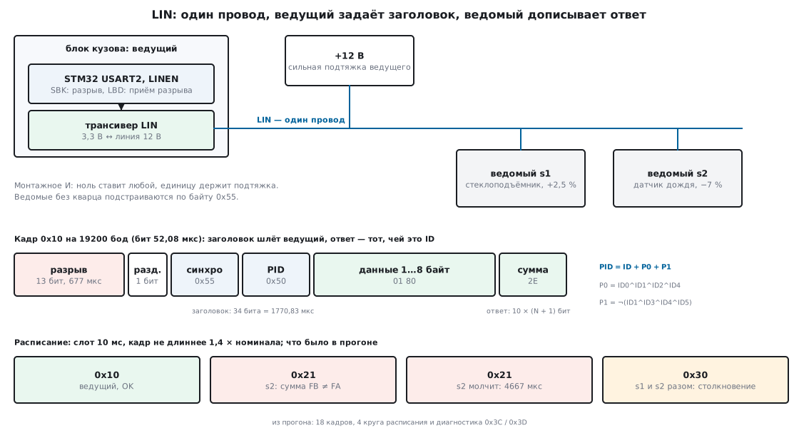
LIN gathers the small body items into one chain: the master sits in the body control unit, the slaves are actuators and sensors that need a couple of bytes once every few tens of milliseconds. That is how it is usually described; the sources contain only one live example — the libopeninv tests work through real LIN frames of the cabin electric heater of the Volkswagen ID.3. Our model has two slaves: the window lifter s1 and the rain sensor s2.
The line is a single wire. As with K-line, it is a wired AND: the one is held by the pull-up to +12 V, the zero is set by whoever transmits, and every transmitter hears itself as an echo. The master's pull-up is stronger, the slaves' is weak. Between the STM32 pin and the line sits a transceiver (for example, TJA1020 and TJA1021 are named): it converts 3.3 V to line levels and back. This section was not checked against transceiver documents — take the pull-up values and levels from the document of the one you fit.
Speeds. The libopeninv driver accepts 9600 or 19200 baud according to its description, the NXP driver recognizes 19200, 14400, 9600, 4800 and 2400 in auto-detection. A bit at 19200 is 52.08 µs, at 9600 — 104.17 µs, at 2400 — 416.67 µs. From here on all numbers are for 19200.
19л.2 The frame: break, 0x55 and the protected identifier
A frame is always started by the master. The header has three parts:
- Break — at least 13 zero bits in a row followed by a delimiter one. An ordinary 0x00 byte gives only 9 zeros (start and 8 bits), so a break cannot be confused with data. At 19200, 13 bits are 677.08 µs; in the model with a 100 ns step the zero on the bus lasted 677.00 µs.
- Sync — the 0x55 byte, which in binary is zeros and ones alternating. On its falling edges a slave without a crystal measures the bit length (19л.5).
- PID — the protected identifier: 6 bits of ID (0…63) and two parity bits.
The parity bits are the same in libopeninv and in the NXP driver:
uint8_t lin_pid(uint8_t id)
{
    id &= 0x3Fu;
    unsigned p0 = BIT(id, 0) ^ BIT(id, 1) ^ BIT(id, 2) ^ BIT(id, 4);
    unsigned p1 = !(BIT(id, 1) ^ BIT(id, 3) ^ BIT(id, 4) ^ BIT(id, 5));
    return (uint8_t)(id | (p0 << 6) | (p1 << 7));
}
P0 = ID0 ^ ID1 ^ ID2 ^ ID4 — into bit 6, P1 = ¬(ID1 ^ ID3 ^ ID4 ^ ID5) — into bit 7. All 64 values (row — the upper part of the ID, column — the offset):
| ID | +0 | +1 | +2 | +3 | +4 | +5 | +6 | +7 |
|---|---|---|---|---|---|---|---|---|
| 0x00 | 80 | C1 | 42 | 03 | C4 | 85 | 06 | 47 |
| 0x08 | 08 | 49 | CA | 8B | 4C | 0D | 8E | CF |
| 0x10 | 50 | 11 | 92 | D3 | 14 | 55 | D6 | 97 |
| 0x18 | D8 | 99 | 1A | 5B | 9C | DD | 5E | 1F |
| 0x20 | 20 | 61 | E2 | A3 | 64 | 25 | A6 | E7 |
| 0x28 | A8 | E9 | 6A | 2B | EC | AD | 2E | 6F |
| 0x30 | F0 | B1 | 32 | 73 | B4 | F5 | 76 | 37 |
| 0x38 | 78 | 39 | BA | FB | 3C | 7D | FE | BF |
The table was built by our lin_pid; the Parity function from libopeninv and
LIN_ProcessParity from the NXP driver, built next to it with g++, gave the same 64 out of 64,
and the four examples from the libopeninv tests (0x00 → 0x80, 0x17 → 0x97,
0x2B → 0x2B, 0x3B → 0xFB) matched. Of the 256 possible bytes only 64 turn out to be valid
PIDs — the slave rejects the other 192 and stays silent.
The diagnostic IDs 0x3C and 0x3D give PIDs 0x3C and 0x7D — exactly these numbers
appear in the NXP code.
19л.3 The response and the checksum
The header is followed by the response: 1…8 data bytes and a checksum. It is sent by whoever owns this ID: the master itself (a command) or one of the slaves (a status). Both sides know the response length in advance — it is not in the frame.
The checksum is an addition of bytes with carry: if the result exceeds 0xFF, 0xFF is subtracted from the sum (the carry returns into the low bit), and at the end everything is inverted. Two variants:
- classic — the data bytes only;
- enhanced — the data and the PID.
uint8_t lin_checksum(uint8_t pid, const uint8_t *d, unsigned n, int enhanced)
{
    unsigned s = enhanced ? pid : 0u;
    while (n--) {
        s += *d++;
        if (s > 0xFFu)
            s -= 0xFFu;             /* перенос из старшего бита — обратно в младший */
    }
    return (uint8_t)~s;
}

int lin_enhanced_for(uint8_t id, int lin2)
{
    return lin2 && id != LIN_ID_MREQ && id != LIN_ID_SRESP;
}
Frames 0x3C and 0x3D always use the classic checksum — that is what a comment in
the NXP driver says, and that is what its LIN_MakeChecksumByte does.
All other frames in our core use the enhanced one (this is LIN 2.x; LIN 1.x
used the classic one for everything — this was not checked against the specification).
An example from the run: the master sends frame 0x10 (PID 0x50) with data 01 80.
The classic checksum is 0x7E, the enhanced one 0x2E; 01 80 2E went onto the bus.
An example from the LIN 2.1 specification quoted by the libopeninv tests: PID 0x4A,
data 55 93 E5 — checksum 0xE6; our code gives the same, as it does for four more vectors
from the same tests (0x72, 0x05, 0x82, 0x5A).
19л.4 The schedule and frame types
The master does not wait for events — it follows a schedule: a table of frames where
each one has its own slot. A slot must fit the longest frame. The header is
34 bits (13 break + 1 delimiter + 10 sync + 10 PID), the response is
10 × (N + 1) bits, where N is the number of data bytes. The nominal time at 19200 and the limit of
1.4 × nominal follow the formulas from the comments of the NXP driver
(LIN_CalcMaxHeaderTimeoutCnt, LIN_CalcMaxResTimeoutCnt):
| N | Nominal | No longer than (1.4 ×) |
|---|---|---|
| 2 | 3333.33 µs | 4667 µs |
| 3 | 3854.17 µs | 5396 µs |
| 4 | 4375.00 µs | 6125 µs |
| 8 | 6458.33 µs | 9042 µs |
The header alone is 1770.83 µs. An 8-byte frame fits into a 10 ms
slot — this is checked by a _Static_assert in lin.h. If no response arrives within
1.4 × nominal, the frame is lost:
    if (m->busy) {
        if (PAST(now, m->f.t_start + m->t_max)) {       /* 1,4 × номинала вышло */
            int r = m->f.n ? LIN_INCOMPLETE : LIN_NO_RESPONSE;
            if (m->tab[m->idx].kind == LIN_EVENT)        /* по событию молчать можно */
                r = m->f.n ? LIN_COLLISION : LIN_NO_NEWS;
            master_finish(m, r, now);
        }
        return;
    }
Frame types. The NXP driver lists four: unconditional, event-triggered, sporadic and diagnostic.
- Unconditional — the ID has exactly one owner, and the response always comes.
- Event-triggered — several slaves may respond to one header, but only those that have something changed; as the first byte of the response the slave puts the PID of its unconditional frame so that the master knows whose it is. No one responding is not an error; two responding is a collision.
- Sporadic — a slot the master fills with a frame of its own choice when it has something to say.
- Diagnostic — the pair 0x3C (master request, 8 bytes) and 0x3D (slave response, 8 bytes), classic checksum. The first byte is the NAD, the node address, followed by a PCI byte, as in an ISO-TP single frame (19в.2), and a UDS service (19д).
The meaning of event-triggered and sporadic frames and the NAD and PCI layout were not taken from a document — the sources contain only the names of the types in NXP and the NAD field in its structures. This is how our master and slaves are built in the run.
The run. A schedule of four frames of 10 ms each: 0x10 (a command to the window lifter, 2 bytes from the master), 0x20 (s1 status, 4 bytes), 0x21 (rain sensor s2, 2 bytes), 0x30 (event-triggered, 3 bytes). The s1 frequency is 2.5 % above nominal, s2 is 7 % below. A slave starts its response 60 µs after receiving the PID — the gap before the response on the bus came out at 34 µs. Four rounds, each with its own trouble:
| Round | What we did | What the master saw |
|---|---|---|
| 1 | everything works | 0x10, 0x20, 0x21 — a response; 0x30 — nobody responded after 5396 µs |
| 2 | s2 corrupts the checksum, s1 has news | 0x21: 07 9C FB arrived, FA expected — a checksum error at 3341 µs; 0x30: 20 41 12 9B from s1 |
| 3 | s2 disconnected | 0x21: no response after 4667 µs, the other frames are fine |
| 4 | s2 is back, both have news | 0x21 responds again; 0x30: 20 00 10 09 on the bus — a collision |
Frame 0x10 took 3333.04 µs (nominal 3333.33; time from the echo, accurate
to a microsecond), 0x20 — 4409.04 µs, 0x21 — 3367.04 µs: the nominal plus
the gap before the response. The collision in round 4 is instructive: s1 sent
20 41 12 9B, s2 — 61 08 9C 09, and the wired AND produced 20 00 10 09. The first
byte 0x20 looks like a response from s1 alone — only the checksum gave it away. After the
schedule the master switched to the diagnostic table: the request
02 03 22 01 02 FF FF FF with checksum D5 (NAD 2, PCI 03, service 0x22, DID
0x0102) and the s2 response 02 04 62 01 02 2A FF FF with checksum 6A, both frames
with the classic checksum. An 8-byte frame took 6458.04 µs.
19л.5 A slave without a crystal: adjusting on 0x55
A cheap slave runs from an internal oscillator, and that drifts by percents. An ordinary UART cannot survive this — in 16.1 the limit is given as 2–3 %. LIN is saved by the 0x55 byte: it has five falling edges (start and bits 1, 3, 5, 7), and from the first to the fifth there are exactly 8 bits. The slave measures this interval with its timer, divides by 8 and uses that bit length until the end of the frame.
In the model the slave receiver does this right after the break. s2, whose
frequency is 7 % lower, counted a bit as 56.004 µs before adjustment, after it
52.087 µs; s1 — 50.813 → 52.087 µs. The NXP driver does the same:
it measures pairs of bits in 0x55, adjacent measurements must not differ by more than
14 % (BIT_RATE_TOLERANCE_UNSYNC = 14), and the speed found must not be more than
2 % away from one of the known ones (AUTOBAUD_BAUDRATE_TOLERANCE).
How much this widens the tolerance was shown by a run of frames 0x10 and 0x20 with one slave while its frequency was shifted from −20 to +20 % in 1 % steps:
| Slave | Delimiter after the break | Frames passed |
|---|---|---|
| without adjustment | 1 bit | from −4 to +5 % |
| with adjustment on 0x55 | 1 bit (F103) | from −17 to +20 %, except −11 % |
| with adjustment on 0x55 | 2 bits (G474) | from −19 to +20 % |
Without adjustment the frame already breaks at −5 and +6 %. With adjustment, failures remained only with a slow slave, and for one reason: its samples are longer than a bit, and a one-bit delimiter can slip between two samples — then the start of the 0x55 byte is taken as a continuation of the break, and the adjustment measures the wrong edges. That is what happened at −11 %. After a break the G4 holds a one on the line for two bits (RM0440, 37.5.13; the F103 — one, RM0008, 27.3.8), and the failure at −11 % disappeared. The run did not go above +20 %.
Auto-baud on the G4. Newer USARTs can measure the speed themselves (RM0440, 37.5.9):
the ABREN bit in CR2 and the ABRMOD = 3 mode — "the 0x55 byte": the speed is refined
on the start bit, on bit 0 and on bit 6, and the ABRF flag reports completion.
Table 343 of RM0440: LIN mode and auto-baud are available on USART1–3 and UART4/5,
not on LPUART1. This path was not checked in our run — the adjustment
is done by the receiver model, not by a model of the G4 USART.
19л.6 On the STM32: the USART in LIN mode
Mode. The LINEN bit in USART_CR2. In LIN mode
STOP[1:0] and CLKEN must be cleared, and in CR3 — SCEN, HDSEL and IREN; the word is 8 bits
(M = 0). So the single-wire HDSEL from 19к is not used here: TX and RX go
to the transceiver separately. The echo remains, though: after transmitting the
header libopeninv looks for its own PID in the receive buffer.
Sending a break. On the F103 — the SBK bit in CR1: 13 zeros and a one
(RM0008, 27.3.8). The bit clears itself during the stop bit of the break.
On the G474 — writing SBKRQ to USART_RQR: 13 zeros and two ones (RM0440,
37.5.13), and the SBKF flag in ISR shows that the break has not gone out yet. In both
cases the break goes after the current byte, so the master sets the request and
immediately gives the transmitter 0x55 and the PID — libopeninv does the same with SBK:
static void hw_break(void *c)
{
    (void)c;
#if defined(STM32F10X_MD)
    USART2->CR1 |= USART_CR1_SBK;                /* 13 нулей и единица-разделитель */
#else
    USART2->RQR = USART_RQR_SBKRQ;               /* 13 нулей и две единицы */
#endif
}
Receiving a break. The break detection circuit works independently of the
receiver: after a start it counts zeros sampled in the middle of the bit, and if
10 (LBDL = 0) or 11 (LBDL = 1) of them accumulate and a one follows,
it sets LBD in SR (on the G4 — LBDF in ISR) and, with LBDIE, an interrupt.
The receiver itself sees the break as a byte with a framing error; the master skips such a byte,
and for a slave it is the signal to start a frame. Enabling it takes three lines:
    USART2->BRR = LIN_BRR;
    USART2->CR2 = USART_CR2_LINEN | USART_CR2_LBDL | USART_CR2_LBDIE;     /* LIN, разрыв 11 бит */
    USART2->CR1 = USART_CR1_TE | USART_CR1_RE | USART_CR1_RXNEIE | USART_CR1_UE;
In the model the threshold is also 11. The 0x00 byte in the s1 response (40 12 00 05) did not become
a break: over 16 schedule frames the master and s1 counted 16 breaks each, s2 —
12 (it was disconnected in round 3).
Divider — by formula 16.2, USART2 on APB1:
| Port | Frequency | 19200 | 9600 | 2400 |
|---|---|---|---|---|
| F103 USART2 | 36 MHz | 1875, exact | 3750, exact | 15000, exact |
| F103 USART1 | 72 MHz | 3750, exact | 7500, exact | 30000, exact |
| G474 USART2 | 170 MHz | 8854: 19200.4 baud, +0.002 % | 17708: 9600.2 baud, +0.002 % | 70833 — does not fit into 16 bits |
BRR is 16 bits, so at 170 MHz you cannot go below 2594.0 baud without a prescaler:
2400 needs PRESC (RM0440, the USART_PRESC register), covered in
16.9. On the F103 at 36 MHz the limit is 549.3 baud.
Build. arm-none-eabi-gcc 12.2.1 (stm-arm:1, -Os) built everything without
warnings: the lin.c core (PID, checksums, master and slave) — 1228 bytes of code
on both the F103 and the G474; the master on USART2 with an interrupt and time from the
DWT cycle counter, lin_stm32.c, — 624 bytes on the F103 and 616 on the G474 plus 312 bytes of
RAM. A _Static_assert checks the dividers 1875 and 8854.
QEMU. The USART model in QEMU 7.2.22 (the stm32vldiscovery board) does not know
LIN mode: after SBK the bit was still set after 100000 polls, only the bytes 55 50 went
to the serial port, there was no break, and SR at the end was 0xC0 (only
TXE and TC). So the logic was checked on the bus model, and the firmware only
by building it.
19л.7 The full code of the core and the master
The master consists of three files of its own: the header lin.h, the core lin.c (PID, checksums,
the scheduled master and the slave) and the master on USART2 lin_stm32.c. Below are all
three in full: lin.c and lin_stm32.c are split into consecutive pieces without gaps —
joined with an empty line, they give the files byte for byte. The pieces from 19л.2,
19л.3, 19л.4 and 19л.6 reappear inside their functions. There is no third-party code.
The sources contain no startup file with a vector table (it needs USART2_IRQHandler), no linker
script and no clock setup: lin_stm32.c is built
only into an object file and assumes the clocks are already configured — 72 MHz on the F103,
170 MHz on the G474. There is no slave on the STM32 in the sources either: lin_slave_break()
and lin_slave_byte() were only run on the bus model lin_host.c — it,
like the QEMU probe qemu_lin.c, is a test bench, not part of the device.
The build is the same as in the check: each file separately for the F103 and the G474.
CMSIS_F1 is the Device/Include directory of the Keil STM32F1xx_DFP 2.4.1 pack (it contains
stm32f10x.h), CMSIS_G4 is Drivers/CMSIS/Device/ST/STM32G4xx/Include
of the STM32G4xx_DFP 1.6.0 pack, CMSIS_CORE is CMSIS/Core/Include from CMSIS
5.9.0 (github.com/ARM-software/CMSIS_5):
for f in lin lin_stm32; do
  arm-none-eabi-gcc -std=c11 -Os -Wall -Wextra -Werror -ffunction-sections -fdata-sections \
    -mcpu=cortex-m3 -mthumb -DSTM32F10X_MD -I. -I$CMSIS_F1 -I$CMSIS_CORE -c $f.c -o F1_$f.o
  arm-none-eabi-gcc -std=c11 -Os -Wall -Wextra -Werror -ffunction-sections -fdata-sections \
    -mcpu=cortex-m4 -mthumb -mfpu=fpv4-sp-d16 -mfloat-abi=hard -DSTM32G474xx \
    -I. -I$CMSIS_G4 -I$CMSIS_CORE -c $f.c -o G4_$f.o
done
Header. The speed, the service IDs 0x3C and 0x3D, the maximum frame length (1.4 × nominal) with a build-time check, the link to the hardware, the schedule and the states of the master and the slave:
/* Раздел 19л: LIN — ведущий с расписанием и ведомый, общее ядро для ПК и STM32.
 * Время — в микросекундах (uint32_t, с переполнением). Ядро не знает про USART:
 * всё железо — через lin_hw_t. */
#ifndef LIN_H
#define LIN_H
#include <stdint.h>

#define LIN_BAUD          19200u
#define LIN_MAX_DATA      8u
#define LIN_ID_MREQ       0x3Cu   /* диагностика: запрос ведущего */
#define LIN_ID_SRESP      0x3Du   /* диагностика: ответ ведомого */
#define LIN_HEADER_BITS   34u     /* 13 разрыв + 1 разделитель + 10 синхро + 10 PID */

/* наибольшая длина кадра: 1,4 × (34 + 10 × (N + 1)) бит, в мкс */
#define LIN_FRAME_MAX_US(n, baud) \
    ((uint32_t)((14ull * (LIN_HEADER_BITS + 10u * ((n) + 1u)) * 1000000ull + 10ull * (baud) - 1u) / (10ull * (baud))))

_Static_assert(LIN_FRAME_MAX_US(8u, 19200u) == 9042u, "8 байт на 19200: не длиннее 9042 мкс");
_Static_assert(LIN_FRAME_MAX_US(8u, 19200u) < 10000u, "кадр из 8 байт помещается в слот 10 мс");

uint8_t lin_pid(uint8_t id);                      /* 6 бит ID + P0, P1 */
int lin_pid_check(uint8_t pid);                   /* ID или -1 при ошибке чётности */
uint8_t lin_checksum(uint8_t pid, const uint8_t *d, unsigned n, int enhanced);
int lin_enhanced_for(uint8_t id, int lin2);       /* 0x3C и 0x3D — всегда классическая */

typedef struct {
    void (*send_break)(void *ctx);                        /* 13 нулей + разделитель */
    void (*send_bytes)(void *ctx, const uint8_t *b, unsigned n);
    void *ctx;
} lin_hw_t;

/* ── ведущий ── */
enum { LIN_PUB_MASTER, LIN_PUB_SLAVE, LIN_EVENT };
enum { LIN_OK, LIN_NO_RESPONSE, LIN_INCOMPLETE, LIN_CHECKSUM, LIN_READBACK, LIN_NO_NEWS, LIN_COLLISION };

typedef struct {
    uint8_t id, len, kind;
    uint16_t slot_ms;
} lin_entry_t;

typedef struct {
    uint8_t id, pid, len, n, result, cs;
    uint8_t data[LIN_MAX_DATA + 1];
    uint32_t t_start, t_end;
} lin_frame_t;

typedef struct {
    lin_hw_t hw;
    const lin_entry_t *tab;
    unsigned tab_n, idx;
    uint32_t baud;
    int lin2;
    int busy;
    uint32_t slot_start, t_max;
    lin_frame_t f;
    uint8_t tx[LIN_MAX_DATA + 3];
    unsigned tx_n, echo_i;
    int (*get_data)(void *ctx, uint8_t id, uint8_t *buf);   /* данные кадров ведущего */
    void (*on_frame)(void *ctx, const lin_frame_t *f);
} lin_master_t;

void lin_master_start(lin_master_t *m, uint32_t now);
void lin_master_poll(lin_master_t *m, uint32_t now);
void lin_master_byte(lin_master_t *m, uint8_t b, int fe, uint32_t now);

/* ── ведомый ── */
typedef struct {
    uint8_t id, len, publish;   /* publish: 1 — отвечает, 0 — слушает, 2 — по событию */
    uint8_t data[LIN_MAX_DATA];
    uint8_t news;               /* для кадра по событию: есть что сказать */
} lin_sframe_t;

typedef struct {
    lin_hw_t hw;
    lin_sframe_t *tab;
    unsigned tab_n;
    int lin2;
    uint8_t nad;
    int state;
    lin_sframe_t *cur;
    uint8_t pid, rx[LIN_MAX_DATA + 1];
    unsigned rx_n, echo_left;
    uint8_t diag[LIN_MAX_DATA];
    int diag_ready;
    int bad_cs_once, mute;      /* порча для прогона */
    unsigned n_ok, n_bad;
    void (*on_frame)(void *ctx, uint8_t id, const uint8_t *d, unsigned n, int ok);
} lin_slave_t;

void lin_slave_break(lin_slave_t *s);
void lin_slave_byte(lin_slave_t *s, uint8_t b, int fe);

#endif
PID and checksums. Two parity bits, the PID check, the checksum with carry and the choice between classic and enhanced:
/* Раздел 19л: ядро LIN — PID, контрольные суммы, ведущий с расписанием, ведомый. */
#include "lin.h"
#include <string.h>

#define PAST(now, t) ((int32_t)((now) - (t)) >= 0)
#define BIT(x, n) (((x) >> (n)) & 1u)

uint8_t lin_pid(uint8_t id)
{
    id &= 0x3Fu;
    unsigned p0 = BIT(id, 0) ^ BIT(id, 1) ^ BIT(id, 2) ^ BIT(id, 4);
    unsigned p1 = !(BIT(id, 1) ^ BIT(id, 3) ^ BIT(id, 4) ^ BIT(id, 5));
    return (uint8_t)(id | (p0 << 6) | (p1 << 7));
}

int lin_pid_check(uint8_t pid)
{
    return lin_pid(pid & 0x3Fu) == pid ? (int)(pid & 0x3Fu) : -1;
}

uint8_t lin_checksum(uint8_t pid, const uint8_t *d, unsigned n, int enhanced)
{
    unsigned s = enhanced ? pid : 0u;
    while (n--) {
        s += *d++;
        if (s > 0xFFu)
            s -= 0xFFu;             /* перенос из старшего бита — обратно в младший */
    }
    return (uint8_t)~s;
}

int lin_enhanced_for(uint8_t id, int lin2)
{
    return lin2 && id != LIN_ID_MREQ && id != LIN_ID_SRESP;
}
Master. A schedule slot: the header (break, 0x55, PID), its own response for master frames, the byte-for-byte echo, reception of the response and the frame result — by the checksum or by the 1.4 × nominal deadline:
/* ════════ ведущий ════════ */

static void master_finish(lin_master_t *m, int result, uint32_t now)
{
    m->f.result = (uint8_t)result;
    m->f.t_end = now;
    m->busy = 0;
    if (m->on_frame)
        m->on_frame(m->hw.ctx, &m->f);
    m->slot_start += (uint32_t)m->tab[m->idx].slot_ms * 1000u;
    m->idx = (m->idx + 1u) % m->tab_n;
}

void lin_master_start(lin_master_t *m, uint32_t now)
{
    m->idx = 0;
    m->busy = 0;
    m->slot_start = now;
}

void lin_master_poll(lin_master_t *m, uint32_t now)
{
    if (m->busy) {
        if (PAST(now, m->f.t_start + m->t_max)) {       /* 1,4 × номинала вышло */
            int r = m->f.n ? LIN_INCOMPLETE : LIN_NO_RESPONSE;
            if (m->tab[m->idx].kind == LIN_EVENT)        /* по событию молчать можно */
                r = m->f.n ? LIN_COLLISION : LIN_NO_NEWS;
            master_finish(m, r, now);
        }
        return;
    }
    if (!PAST(now, m->slot_start))
        return;
    const lin_entry_t *e = &m->tab[m->idx];
    memset(&m->f, 0, sizeof m->f);
    m->f.id = e->id;
    m->f.pid = lin_pid(e->id);
    m->f.len = e->len;
    m->f.t_start = now;
    m->t_max = LIN_FRAME_MAX_US(e->len, m->baud);
    m->tx[0] = 0x55u;
    m->tx[1] = m->f.pid;
    m->tx_n = 2;
    if (e->kind == LIN_PUB_MASTER) {                     /* ответ шлёт сам ведущий */
        m->get_data(m->hw.ctx, e->id, &m->tx[2]);
        m->tx[2 + e->len] = lin_checksum(m->f.pid, &m->tx[2], e->len, lin_enhanced_for(e->id, m->lin2));
        m->tx_n += e->len + 1u;
    }
    m->echo_i = 0;
    m->busy = 1;
    m->hw.send_break(m->hw.ctx);
    m->hw.send_bytes(m->hw.ctx, m->tx, m->tx_n);
}

void lin_master_byte(lin_master_t *m, uint8_t b, int fe, uint32_t now)
{
    if (!m->busy || fe)
        return;                                   /* сам разрыв приходит ошибкой кадра */
    if (m->echo_i < m->tx_n) {                    /* своё эхо: читаем обратно */
        if (b != m->tx[m->echo_i]) {
            master_finish(m, LIN_READBACK, now);
            return;
        }
        if (++m->echo_i == m->tx_n && m->tab[m->idx].kind == LIN_PUB_MASTER) {
            memcpy(m->f.data, &m->tx[2], m->f.len + 1u);
            m->f.n = (uint8_t)(m->f.len + 1u);
            m->f.cs = m->tx[2 + m->f.len];
            master_finish(m, LIN_OK, now);
        }
        return;
    }
    m->f.data[m->f.n++] = b;
    if (m->f.n < m->f.len + 1u)
        return;
    m->f.cs = b;
    int enh = lin_enhanced_for(m->f.id, m->lin2);
    int ok = lin_checksum(m->f.pid, m->f.data, m->f.len, enh) == b;
    if (m->tab[m->idx].kind == LIN_EVENT)
        master_finish(m, ok ? LIN_OK : LIN_COLLISION, now);
    else
        master_finish(m, ok ? LIN_OK : LIN_CHECKSUM, now);
}
Slave. A break arrives as a byte with a framing error and resets the state machine; then 0x55, the PID with a parity check, a response or reception, diagnostics 0x3C/0x3D with service 0x22:
/* ════════ ведомый ════════ */

enum { S_BREAK, S_SYNC, S_PID, S_DATA, S_SEND };

void lin_slave_break(lin_slave_t *s)
{
    s->state = S_SYNC;                            /* всё прежнее — забыть */
}

static void slave_send(lin_slave_t *s, const uint8_t *d, unsigned n, int enh)
{
    uint8_t out[LIN_MAX_DATA + 1];
    memcpy(out, d, n);
    out[n] = lin_checksum(s->pid, d, n, enh);
    if (s->bad_cs_once) {
        out[n] ^= 0x01u;
        s->bad_cs_once = 0;
    }
    s->echo_left = n + 1u;
    s->state = S_SEND;
    s->hw.send_bytes(s->hw.ctx, out, n + 1u);
}

void lin_slave_byte(lin_slave_t *s, uint8_t b, int fe)
{
    if (fe) {
        s->state = S_BREAK;
        return;
    }
    switch (s->state) {
    case S_SYNC:
        s->state = (b == 0x55u) ? S_PID : S_BREAK;
        break;
    case S_PID: {
        int id = lin_pid_check(b);
        s->state = S_BREAK;
        if (id < 0 || s->mute)
            return;                               /* чётность не сошлась — молчим */
        s->pid = b;
        s->cur = 0;
        for (unsigned i = 0; i < s->tab_n; i++)
            if (s->tab[i].id == id)
                s->cur = &s->tab[i];
        if (id == LIN_ID_SRESP && s->diag_ready) {
            s->diag_ready = 0;
            slave_send(s, s->diag, 8, 0);
            return;
        }
        if (id == LIN_ID_MREQ) {
            s->cur = 0;
            s->rx_n = 0;
            s->state = S_DATA;
            return;
        }
        if (!s->cur)
            return;
        if (s->cur->publish == 1 || (s->cur->publish == 2 && s->cur->news)) {
            s->cur->news = 0;
            slave_send(s, s->cur->data, s->cur->len, lin_enhanced_for((uint8_t)id, s->lin2));
        } else if (s->cur->publish == 0) {
            s->rx_n = 0;
            s->state = S_DATA;
        }
        break;
    }
    case S_DATA: {
        unsigned len = s->cur ? s->cur->len : 8u;
        s->rx[s->rx_n++] = b;
        if (s->rx_n < len + 1u)
            break;
        s->state = S_BREAK;
        uint8_t id = s->pid & 0x3Fu;
        int ok = lin_checksum(s->pid, s->rx, len, lin_enhanced_for(id, s->lin2)) == s->rx[len];
        ok ? s->n_ok++ : s->n_bad++;
        if (ok && s->cur)
            memcpy(s->cur->data, s->rx, len);
        if (ok && !s->cur && s->rx[0] == s->nad && s->rx[2] == 0x22u) {
            /* диагностика: NAD, PCI, служба 0x22 (19д) — готовим ответ на 0x3D */
            const uint8_t r[8] = {s->nad, 0x04u, 0x62u, s->rx[3], s->rx[4], 0x2Au, 0xFFu, 0xFFu};
            memcpy(s->diag, r, 8);
            s->diag_ready = 1;
        }
        if (s->on_frame)
            s->on_frame(s->hw.ctx, id, s->rx, len, ok);
        break;
    }
    case S_SEND:
        if (s->echo_left && --s->echo_left == 0)
            s->state = S_BREAK;                   /* своё эхо дослушали */
        break;
    default:
        break;
    }
}
USART2 in LIN mode. Time from the DWT cycle counter, the pins, the divider,
LINEN and the 11-bit break threshold:
/* Раздел 19л: ведущий LIN на USART2 (PA2 — TX, PA3 — RX) через трансивер.
 * STM32F103: PCLK1 = 36 МГц, HCLK = 72 МГц.  STM32G474: PCLK1 = HCLK = 170 МГц.
 * Ядро lin.c то же, что прогонялось на модели шины. */
#include "lin.h"
#if defined(STM32F10X_MD)
#include "stm32f10x.h"
#define PCLK1 36000000u
#define HCLK  72000000u
#else
#include "stm32g4xx.h"
#define PCLK1 170000000u
#define HCLK  170000000u
#endif

#define LIN_BRR ((PCLK1 + LIN_BAUD / 2u) / LIN_BAUD)
_Static_assert(LIN_BRR == (PCLK1 == 36000000u ? 1875u : 8854u), "делитель на 19200 бод");

static lin_master_t M;
static volatile uint16_t ring[16];               /* байт | ошибка кадра << 8 */
static volatile uint32_t ring_t[16];
static volatile unsigned rh, rt;
static const uint8_t *tx_p;
static volatile unsigned tx_n;
static uint32_t cyc_last, now_us;

static uint32_t micros(void)                     /* микросекунды из счётчика тактов DWT */
{
    uint32_t d = DWT->CYCCNT - cyc_last;
    uint32_t u = d / (HCLK / 1000000u);
    cyc_last += u * (HCLK / 1000000u);
    now_us += u;
    return now_us;
}

static void usart2_lin_init(void)
{
#if defined(STM32F10X_MD)
    RCC->APB2ENR |= RCC_APB2ENR_IOPAEN;
    RCC->APB1ENR |= RCC_APB1ENR_USART2EN;
    GPIOA->CRL = (GPIOA->CRL & ~0xFF00u) | 0x4B00u;   /* PA2 — выход AF, PA3 — вход */
#else
    RCC->AHB2ENR |= RCC_AHB2ENR_GPIOAEN;
    RCC->APB1ENR1 |= RCC_APB1ENR1_USART2EN;
    GPIOA->AFR[0] = (GPIOA->AFR[0] & ~0xFF00u) | 0x7700u;               /* AF7 */
    GPIOA->MODER = (GPIOA->MODER & ~0xF0u) | 0xA0u;
#endif
    USART2->BRR = LIN_BRR;
    USART2->CR2 = USART_CR2_LINEN | USART_CR2_LBDL | USART_CR2_LBDIE;     /* LIN, разрыв 11 бит */
    USART2->CR1 = USART_CR1_TE | USART_CR1_RE | USART_CR1_RXNEIE | USART_CR1_UE;
    NVIC_EnableIRQ(USART2_IRQn);
}
Break, transmission and interrupt. The break is SBK on the F103 and SBKRQ on the G474,
the bytes go by TXE, the received ones go into a ring buffer together with the framing error and the time:
static void hw_break(void *c)
{
    (void)c;
#if defined(STM32F10X_MD)
    USART2->CR1 |= USART_CR1_SBK;                /* 13 нулей и единица-разделитель */
#else
    USART2->RQR = USART_RQR_SBKRQ;               /* 13 нулей и две единицы */
#endif
}

static void hw_bytes(void *c, const uint8_t *b, unsigned n)
{
    (void)c;
    tx_p = b;                                    /* буфер ядра живёт до конца кадра */
    tx_n = n;
    USART2->CR1 |= USART_CR1_TXEIE;              /* байты пойдут после разрыва */
}

void USART2_IRQHandler(void)
{
#if defined(STM32F10X_MD)
    uint32_t sr = USART2->SR;
    if (sr & USART_SR_LBD)
        USART2->SR = (uint16_t)~USART_SR_LBD;    /* разрыв ведущему не нужен: только сброс */
    if (sr & USART_SR_RXNE) {
        ring[rt % 16u] = (uint16_t)((USART2->DR & 0xFFu) | ((sr & USART_SR_FE) ? 0x100u : 0u));
        ring_t[rt % 16u] = micros();
        rt++;
    }
    if ((USART2->CR1 & USART_CR1_TXEIE) && (sr & USART_SR_TXE)) {
        if (tx_n) { USART2->DR = *tx_p++; tx_n--; }
        else USART2->CR1 &= ~USART_CR1_TXEIE;
    }
#else
    uint32_t isr = USART2->ISR;
    if (isr & USART_ISR_LBDF)
        USART2->ICR = USART_ICR_LBDCF;
    if (isr & USART_ISR_RXNE) {
        ring[rt % 16u] = (uint16_t)((USART2->RDR & 0xFFu) | ((isr & USART_ISR_FE) ? 0x100u : 0u));
        ring_t[rt % 16u] = micros();
        rt++;
        USART2->ICR = USART_ICR_FECF | USART_ICR_ORECF;
    }
    if ((USART2->CR1 & USART_CR1_TXEIE) && (isr & USART_ISR_TXE)) {
        if (tx_n) { USART2->TDR = *tx_p++; tx_n--; }
        else USART2->CR1 &= ~USART_CR1_TXEIE;
    }
#endif
}
Schedule and main loop. Four frames of 10 ms each, the data of frame 0x10,
the last responses go into the last array for the debugger:
static const lin_entry_t TAB[] = {
    {0x10, 2, LIN_PUB_MASTER, 10}, {0x20, 4, LIN_PUB_SLAVE, 10},
    {0x21, 2, LIN_PUB_SLAVE, 10},  {0x30, 3, LIN_EVENT, 10},
};

static int get_data(void *c, uint8_t id, uint8_t *buf)
{
    (void)c;
    if (id == 0x10) { buf[0] = 0x01; buf[1] = 0x80; return 2; }
    return 0;
}

volatile lin_frame_t last[4];                    /* последние ответы: смотреть отладчиком */
static void on_frame(void *c, const lin_frame_t *f)
{
    (void)c;
    last[(f->id == 0x10) ? 0 : (f->id == 0x20) ? 1 : (f->id == 0x21) ? 2 : 3] = *f;
}

int main(void)
{
    CoreDebug->DEMCR |= CoreDebug_DEMCR_TRCENA_Msk;
    DWT->CYCCNT = 0;
    DWT->CTRL |= DWT_CTRL_CYCCNTENA_Msk;
    usart2_lin_init();
    M.hw.send_break = hw_break;
    M.hw.send_bytes = hw_bytes;
    M.tab = TAB;
    M.tab_n = 4;
    M.baud = LIN_BAUD;
    M.lin2 = 1;
    M.get_data = get_data;
    M.on_frame = on_frame;
    lin_master_start(&M, micros());
    for (;;) {
        while (rh != rt) {
            uint16_t v = ring[rh % 16u];
            uint32_t t = ring_t[rh % 16u];
            rh++;
            lin_master_byte(&M, (uint8_t)v, v >> 8, t);
        }
        __disable_irq();                         /* micros() зовут и из прерывания */
        uint32_t t = micros();
        __enable_irq();
        lin_master_poll(&M, t);
    }
}
19л.8 Pitfalls
The delimiter slipped through. A slow slave with adjustment on 0x55 at −11 %
lost a frame: the samples came every 1.12 bits, and the one-bit delimiter
fell between them. A two-bit delimiter, as on the G4, closed the hole.
On the F103 the delimiter can be lengthened in software: wait until SBK
clears, and only then load 0x55 (in the model this is the same case as
two bits on the G4; not tested on hardware).
A collision looks like a response. Two slaves responded to an event-triggered frame at once, and the first byte 0x20 matched the PID of the s1 frame. Do not trust the content until the checksum matches; after a collision, poll the unconditional frames of everyone who could have responded, one by one.
The wrong checksum for diagnostics. The Checksum function from libopeninv always
adds the PID. For the 0x3C request it gave 0x99, while the NXP driver and our code gave
0xD5; for the 0x3D response — 0xEC instead of 0x6A. For 0x3C and 0x3D use only
the classic checksum.
A slave stays silent on its own ID. Check the PID: only 64 of the 256 bytes are valid, and a slave with wrong parity does not respond at all. A common mistake is to put the ID without parity bits into the header.
Silence on an event-triggered frame is not an error. An event-triggered frame without a response is normal: the master waits 1.4 × nominal (5396 µs for 3 bytes) and moves on. But an unconditional frame without a response means the node is gone, and that must be reported.
A slot shorter than the frame. An 8-byte frame can stretch to 9042 µs. A 10 ms slot fits it, a 5 ms slot does not: the next header will run into the response.
LIN mode and the single-wire USART together. HDSEL must be
cleared in LIN mode (RM0008, RM0440) — route TX and RX to the transceiver separately, as
libopeninv does.
2400 baud on the G4. At 170 MHz the divider 70833 does not fit into the 16 bits of BRR —
enable PRESC.
19л.9 Summary
- LIN is a single wire, a wired AND, one master with a schedule; a bit at 19200 is 52.08 µs, at 9600 — 104.17, at 2400 — 416.67.
- Header: a 13-bit break (677.08 µs) and a delimiter, 0x55, PID — in total 34 bits, 1770.83 µs.
- PID = ID + P0 (ID0^ID1^ID2^ID4) + P1 (¬(ID1^ID3^ID4^ID5)): 64 valid bytes out of 256, 0x3C → 0x3C, 0x3D → 0x7D; the table matched libopeninv and NXP 64 out of 64.
- The checksum uses carry and inversion; the enhanced one includes the PID, for 0x3C and
0x3D only the classic one:
01 80in frame 0x10 give 0x7E and 0x2E. - A frame is no longer than 1.4 × nominal: 4667 µs for 2 bytes, 9042 µs for 8 — a 10 ms slot fits any of them.
- Adjustment on 0x55 widened the slave tolerance from −4…+5 % to −19…+20 % (with a 2-bit delimiter).
- STM32:
LINEN,LBDL,LBD/LBDF,SBK/SBKRQ; BRR 1875 at 36 MHz and 8854 at 170 MHz; the core is 1228 bytes of code, the master 624 bytes on the F103.
Next: section 19м "rusEFI from the inside: spark and injection by crank angle — dwell, advance and an event queue on a single timer".