Section 19 took CAN as far as frames and filters, 19б — as far as CANopen, where everything
you need fits into the 8 bytes of a frame, and a long SDO value is cut into
segments in its own way. In a car that will not do: the vehicle identification number (VIN) is 17 characters,
a list of trouble codes is tens of bytes, a firmware block is kilobytes. All of this
travels between the tester and the car's ECUs over ISO-TP — the transport from
the ISO 15765-2 standard. It cuts a message into frames and numbers them, and the
receiver tells the transmitter how fast to send.
Here: the four frame types byte by byte, flow control (BS and STmin),
lengths up to 4095 bytes and beyond, the diagnostic addresses in a car (0x7DF, 0x7E0,
0x7E8, 0x18DB33F1), padding a frame to 8 bytes, timeouts and what happens
when no answer arrives. At the end — the open-source isotp-c library on top of bxCAN on the
STM32F103: how to hook it up and how much space it takes.
the diagnostic device, the electronic control unit
19в.1 Why 8 bytes are not enough
A classic CAN frame carries from 0 to 8 bytes of data (RM0090, Fig. 347). For
a sensor or a command to a drive that is enough. For diagnostics it is not: the response to
a VIN request is 3 header bytes and 17 characters, 20 bytes. The message
length in ISO-TP goes up to 4095 bytes in the normal encoding and up to 32 bits
in the extended one; the Zephyr description says plainly "theoretically up to four
gigabytes".
ISO-TP does three things:
cuts the message into frames and writes its length into the first one, and a number into each
following one;
reassembles it on the receiving side and checks that the numbers are consecutive;
gives the receiver a brake: it replies with a flow control frame — how many
frames to send in a row and with what gap, or "wait", or "it will not fit".
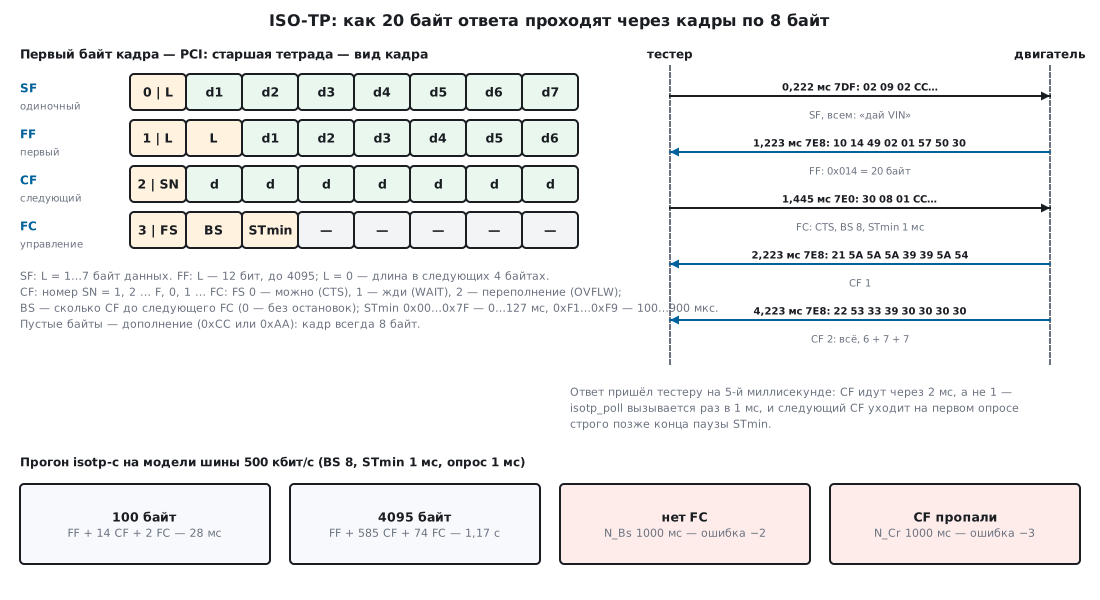
A short message (up to 7 bytes) goes out as a single frame with no replies at all —
that is how the two-byte VIN request went out in the run. A long one goes as
a first frame, then a flow control frame from the receiver, then the consecutive frames.
19в.2 The four frame types byte by byte
The first byte of a frame is the PCI. The upper nibble is the frame type, the lower one is
the length, the number or the status (python-obd takes the frame type exactly this way:
frame.data[0] & 0xF0):
Type
Upper nibble
What follows
Data in the frame
SF, single
0
lower nibble — length 1…7
up to 7 bytes
FF, first
1
12 bits of length: the lower nibble and byte 1
6 bytes
CF, consecutive
2
lower nibble — number SN
7 bytes
FC, flow control
3
lower nibble — FS, byte 1 — BS, byte 2 — STmin
none
The "VIN request" exchange from the run (the tester asks everyone, the engine answers;
the time is the end of the frame on a 500 kbit/s bus):
Time
Identifier
Bytes
What it is
0.222 ms
0x7DF
02 09 02 CC CC CC CC CC
SF: 2 bytes, service 09, parameter 02
1.223 ms
0x7E8
10 14 49 02 01 57 50 30
FF: length 0x014 = 20, the first 6 bytes
1.445 ms
0x7E0
30 08 01 CC CC CC CC CC
FC: go ahead, BS 8, STmin 1 ms
2.223 ms
0x7E8
21 5A 5A 5A 39 39 5A 54
CF 1: another 7 bytes
4.223 ms
0x7E8
22 53 33 39 30 30 30 30
CF 2: the last 7 bytes
6 + 7 + 7 = 20 — the message is reassembled, the tester received 20 bytes, and they matched
the ones sent. The tester sends the flow control frame not to 0x7DF but to the engine's physical
address 0x7E0: a functional request can only be a single
frame (the isotp-c description says so too), after that the conversation is one to
one.
The SN number in a CF starts at 1, grows to F and wraps to 0. In the run of
a 4095-byte message, the CF with byte 2F was followed by 20, then 21 — the isotp-c
receiver expects exactly that number, otherwise it drops the message with the error
"wrong sequence number".
Lengths above 4095. The 12 length bits of an FF are enough for 4095 bytes. For a larger
message the FF writes length 0, and the real one goes into the next 4 bytes, most significant
first. In the run, a 4096-byte message started like this:
10 00 00 00 10 00 01 08 — after 0x00001000 = 4096, the first frame had
room for only 2 bytes of data. A 4095-byte message still uses
the normal encoding: 1F FF … and 6 bytes of data.
19в.3 Flow control: FS, BS and STmin
The flow control frame (FC) is sent by the receiver right after the FF, and then after
every BS CF frames. It has three fields.
FS is the status: 0 — go ahead (CTS), 1 — wait (WAIT), 2 — overflow
(OVFLW). The transmitter tolerates WAIT a limited number of times: in isotp-c the
default is 1 (ISO_TP_MAX_WFT_NUMBER), in Zephyr — 10; after that it gives up.
OVFLW means "the message will not fit". In the run the tester had a buffer of 4095
bytes, and the ECU started sending 4096: the tester answered the FF with the frame
32 00 00 CC CC CC CC CC, and the transfer ended with an overflow error (−8)
on both sides — after 0.444 ms, without waiting for a single CF.
BS is how many CFs to send before the next FC; 0 — the whole message without
stops. With BS 8, a 100-byte message is an FF, 14 CFs (6 + 13 × 7 + 3)
and 2 FCs: after the FF and after the eighth CF. 17 frames in total. 4095 bytes — an FF,
585 CFs and 74 FCs, 660 frames.
STmin is the minimum gap between CFs, one byte with two ranges.
How isotp-c interprets them (a run of its own functions):
The same two ranges and "reserved" between them are written in Zephyr's isotp.h
and in linux/can/isotp.h. In the other direction, from microseconds to a byte, isotp-c
encodes 500 µs as 0xF5, 1500 µs as 0x01 (it rounds down to
milliseconds), 950 µs as 0x00, and 128000 µs, which no longer
fits, also as 0x00: you asked for a gap and got "no gap".
19в.4 Addresses in a car and frame padding
ISO-TP has no address field of its own — the address is set by the CAN identifier. In
OBD-II diagnostics of passenger cars two sets are used:
What
11 bits
29 bits
request to all ECUs (functional)
0x7DF
0x18DB33F1
request to one ECU (physical)
0x7E0…0x7E7
0x18DAxxF1, xx — ECU number
ECU response
request + 8: 0x7E8…0x7EF
0x18DAF1xx
0x7DF and 0x18DB33F1 as functional addresses are written in the elm327-emulator,
and so are the "request — response" pairs: engine 0x7E0/0x7E8, transmission 0x7E1/0x7E9,
hybrid ECU 0x7E2/0x7EA. python-obd recognizes a response by bit 0x08 in
the identifier and takes the ECU number from the three lower bits — hence 0x7E8…0x7EF.
A 29-bit identifier is split into fields (the scheme from Zephyr's isotp.h,
"fixed addressing according to SAE J1939"):
Bits
28…26
25…24
23…16
15…8
7…0
Field
priority
EDP, DP
address type
target
source
0x18DB33F1
6
0
0xDB — functional
0x33 — all
0xF1 — tester
0x18DA10F1
6
0
0xDA — physical
0x10
0xF1
python-obd parses these bytes the same way: DB — functional, DA —
physical, 0x33 — all, 0xF1 — tester. The run with 29-bit addresses gave
the same exchange as with 11-bit ones, only the identifiers differ, and every
frame is 20 bits longer: 67 + 8n bits instead of 47 + 8n (RM0090, Fig. 347,
plus 3 bits of interframe space) — the VIN response arrived within the same 5 ms, the frames shifted by
tens of microseconds.
Extended addressing puts the target address in the first
data byte, and the PCI moves one byte along: an SF has 6 data bytes left instead of 7
(that is how Zephyr calculates it: frame length minus 2). isotp-c does not support it —
its code has neither a field nor a flag for this byte. The standard also describes
mixed addressing; neither isotp-c nor Zephyr treats it as a separate mode,
and it is not covered here.
Padding. By default isotp-c sends a frame of exactly the length needed:
the VIN request without padding went out in the run as 7DF [3] 02 09 02, the FC —
as [3] 30 08 00. Car ECUs expect an 8-byte frame: AUTOSAR requires
length 8 for SF, FC and the last CF (that is how the flag
ISOTP_REQUIRE_RX_PADDING is described in Zephyr), and rusEFI always answers an OBD request
with an 8-byte frame. In isotp-c padding is enabled with ISO_TP_FRAME_PADDING;
the default byte is 0xAA. Zephyr and Linux use 0xCC: Zephyr — "as
recommended by Bosch", Linux — to avoid stuff bits.
How many stuff bits there actually are — frame 0x7DF 02 09 02 and 5 padding
bytes, counted by the CAN rules and cross-checked against canframelen.c from
can-utils:
Padding
Stuff bits
Frame length, bits
0x00
13
124
0x55
5
116
0xAA
5
116
0xCC
6
117
0xFF
14
125
Without stuffing the frame is 111 bits. Zeros and ones give the most stuff bits;
0xAA, 0x55 and 0xCC add almost nothing — the stuff bits that remain come from
the identifier and the CRC.
19в.5 Timing and timeouts
The standard defines timeouts after which a side drops the message.
Zephyr sets all three to 1000 ms by default with a reference to
ISO 15765-2:
Timeout
Who waits
For what
N_As, N_Ar
the frame transmitter
until the CAN driver sends the frame
N_Bs
the message transmitter
the next FC
N_Cr
the message receiver
the next CF
isotp-c has one common timeout ISO_TP_DEFAULT_RESPONSE_TIMEOUT_US
for both N_Bs and N_Cr, by default 100000 µs, that is 100 ms;
N_As is not tracked. To match 1000 ms, you set 1000000. What happened in
the run:
Scenario
Result
When
the ECU sends an FF, there is no tester on the bus
transmitter: error −2, N_Bs timeout
1001 ms
the same with the default setting
transmitter: error −2
101 ms
the ECU went silent after 5 CFs of 14
receiver: error −3, N_Cr timeout
1010 ms
The extra millisecond is the polling step: isotp_poll() was called once every 1 ms, and
it notices an expiry strictly after the deadline. In the last row the last
CF arrived at 9.223 ms, the deadline expired at 1009.223 ms, and it was noticed at 1010 ms.
Neither side tells the other "I give up": the receiver simply discards
the partially assembled message, and the transmitter sets the "error" state — what to do
next is up to the program.
The polling step decides the speed. isotp-c sends CFs only from isotp_poll()
and no more than one per call, and the next one — on the first call strictly after
the end of the STmin gap. A run with BS 8 and STmin 1 ms:
Message
Polling
CF step
Until received
100 bytes
1 ms
2000 µs
28 ms
100 bytes
0.1 ms
1100 µs
15.1 ms
4095 bytes
1 ms
2000 µs
1.17 s
And without the brake — BS 0, STmin 0:
Message
Polling
CF step
Until received
4095 bytes
1 ms
1000 µs
586 ms
4095 bytes
0.1 ms
222…444 µs
130.9 ms
4095 bytes
0.01 ms
222…444 µs
130.77 ms
222 µs is the 8-byte frame itself: 111 bits of 2 µs each. With polling once
a millisecond, 585 CFs took 586 ms — 4.5 times slower than the bus allows.
444 µs is where the tester's FC got onto the bus between two CFs: with BS 0
isotp-c still sends FC 30 00 00 after every 256 CFs — its block counter
is 8-bit. In the run there were two such FCs, and they do not bother the transmitter.
19в.6 isotp-c on top of bxCAN on the F103
The library is a single file isotp.c plus headers, with no dynamic memory.
It needs three functions from the program: isotp_user_send_can() — send
a frame, isotp_user_get_us() — the time in microseconds, isotp_user_debug() —
messages, it can be empty. The program itself calls:
isotp_init_link() — the link: its own transmit identifier and two buffers;
isotp_send() / isotp_send_with_id() — send (the second one with a different
identifier, for example 0x7DF);
isotp_on_can_message() — hand the library a received frame of this
link: it does not look at identifiers, filtering is the program's job;
isotp_poll() — advance the transmission and check the timeouts;
isotp_receive() — take the assembled message.
Below is a tester on the STM32F103C8 (file isotp19v_f103.c): once a second it
asks all ECUs for the VIN and assembles the engine's response. A frame is sent
into a free bxCAN mailbox; if all three are busy, the library retries on
the next poll. An identifier greater than 0x7FF is treated as 29-bit —
isotp-c passes only a number, and whether it is 11 or 29 bits is decided by this function:
int isotp_user_send_can(const uint32_t id, const uint8_t *data, const uint8_t size)
{
    uint32_t box = (CAN1->TSR & CAN_TSR_CODE) >> 24;   /* номер свободного ящика */
    uint32_t lo = 0, hi = 0;
    if ((CAN1->TSR & (CAN_TSR_TME0 << box)) == 0u) {
        return ISOTP_RET_NOSPACE;                      /* все три заняты: библиотека повторит */
    }
    for (uint32_t i = 0; i < size; i++) {
        if (i < 4u) lo |= (uint32_t)data[i] << (8u * i);
        else        hi |= (uint32_t)data[i] << (8u * (i - 4u));
    }
    CAN1->sTxMailBox[box].TDTR = size;
    CAN1->sTxMailBox[box].TDLR = lo;
    CAN1->sTxMailBox[box].TDHR = hi;
    CAN1->sTxMailBox[box].TIR = (id > 0x7FFu)
        ? ((id << 3) | CAN_TI0R_IDE | CAN_TI0R_TXRQ)   /* 29 бит: EXID с бита 3 */
        : ((id << 21) | CAN_TI0R_TXRQ);                /* 11 бит: STID с бита 21 */
    return ISOTP_RET_OK;
}
By default the three bxCAN mailboxes are sent not in the order they were written but by
identifier, and with equal identifiers the mailbox with the lower number goes first (RM0090, 32.7.1).
All CFs of one message have the same identifier, and a CF written to mailbox 0
later will overtake one written earlier to mailbox 2 — the receiver will see a wrong
number. The TXFP bit switches the mailboxes to a queue in write order —
RM0090 says exactly that: useful for segmented transmission. The filter is
a single 32-bit one in mask mode: it passes 0x7E8…0x7EF and only 11-bit identifiers:
CAN1->MCR = CAN_MCR_INRQ | CAN_MCR_TXFP | CAN_MCR_ABOM; /* TXFP: ящики уходят в порядке записи */
The receive interrupt only copies the frame into a ring of 16 frames. All calls to
the library are made from the main loop: for one link the calls must not
overlap (the isotp-c description requires this), and isotp_on_can_message()
called from an interrupt could cut into the middle of isotp_poll():
    for (;;) {
        while (tail != head) {                /* кадры из прерывания — в библиотеку */
            rx_frame *f = &ring[tail % 16u];
            if (f->id == ID_RESP) {
                isotp_on_can_message(&link, f->d, f->len);
            }
            tail++;
        }
        isotp_poll(&link);                    /* тайм-ауты и следующие CF */
isotp_poll() is called here on every pass of the loop, not once a
millisecond — otherwise your own long transfer would go at the polling speed
(19в.5). The time for the library is the SysTick millisecond count plus the current
value of its counter.
The build with arm-none-eabi-gcc 12.2 (-Os, -Wall -Wextra -Werror, with
ISO_TP_FRAME_PADDING, 0xCC, a 1000000 µs timeout and
ISO_TP_NO_FORMATTED_ERRORS — no snprintf) passed without warnings:
the whole firmware is 3288 bytes of flash and 8620 bytes of RAM, of which
8190 are two buffers of 4095 bytes (the link's receive buffer and a copy of the response).
isotp.c itself is 2063 bytes of code, the link structure IsoTpLink is 96 bytes.
For comparison, in isotp_config.h the author gives 2091 bytes for Cortex-M4
without formatted messages. The F407 has bxCAN with the same registers (RM0090);
for it the clocking, the pins and the header change; that build was not
checked.
19в.7 The full tester code for the F103
Here is all of isotp19v_f103.c in order, except isotp_user_send_can():
it is given in full in 19в.6 and sits in the file right after
isotp_user_get_us(). Together with isotp-c and the linker script, this is the whole
tester firmware. Five files are needed from isotp-c: isotp.c, isotp.h,
isotp_config.h, isotp_defines.h, isotp_user.h —
github.com/SimonCahill/isotp-c, version v1.9.3 (commit 1fc19e2), unmodified.
The build is the same command as in the check. CMSIS_F1 is the Device/Include directory
of the Keil STM32F1xx_DFP 2.4.1 pack (it contains stm32f10x.h), CMSIS_CORE is
CMSIS/Core/Include from CMSIS 5.9.0 (github.com/ARM-software/CMSIS_5):
The start of the file and the time. CAN dividers with a build-time check, the OBD
addresses, the link buffers and a ring of 16 frames. isotp_user_get_us() reads
the millisecond count and the SysTick counter; the loop repeats the read if
the SysTick interrupt managed to change ms between the two reads:
/* Раздел 19в — ISO-TP (isotp-c, MIT) поверх bxCAN STM32F103C8: тестер спрашивает блоки машины.
 *   PB8/PB9 — CAN_RX/CAN_TX после ремапа; кварц 8 МГц × 9 = 72 МГц, APB1 = 36 МГц;
 *   500 кбит/с: 36 МГц / 4 = 9 МГц, 1 + 15 + 2 = 18 квантов, точка выборки 16/18.
 * Прерывание приёма только складывает кадр в кольцо; isotp_on_can_message и isotp_poll
 * вызываются из одного места — главного цикла: библиотека требует, чтобы вызовы
 * для одного канала не перекрывались. */
#include "stm32f10x.h"
#include "isotp.h"

#define FCAN     36000000u
#define BRP      4u
#define TS1      15u
#define TS2      2u
_Static_assert(FCAN / (BRP * (1u + TS1 + TS2)) == 500000u, "500 кбит/с ровно");

#define ID_FUNC  0x7DFu                 /* функциональный запрос: всем блокам */
#define ID_REQ   0x7E0u                 /* физический запрос двигателю */
#define ID_RESP  0x7E8u                 /* ответ двигателя = 0x7E0 + 8 */

typedef struct { uint32_t id; uint8_t len; uint8_t d[8]; } rx_frame;

static IsoTpLink link;
static uint8_t t_tx[64], t_rx[4095];
static volatile uint32_t ms;
static rx_frame ring[16];
static volatile uint32_t head, tail;

void isotp_user_debug(const char *message, ...) { (void)message; }

void SysTick_Handler(void)
{
    ms++;
}

/* микросекунды из счёта мс и текущего значения SysTick (он считает вниз от 71999) */
uint32_t isotp_user_get_us(void)
{
    uint32_t m, v;
    do {
        m = ms;
        v = SysTick->VAL;
    } while (m != ms);
    return m * 1000u + (71999u - v) / 72u;
}
The receive interrupt. It drains FIFO 0 to the bottom: the identifier
(11 or 29 bits depending on the IDE bit), the length, 8 data bytes — and releases the FIFO
mailbox with the RFOM0 bit. The ring must not overflow: with 16 unread
frames, a new one is written over the oldest, and head does not advance.
72 MHz clock and bxCAN. An 8 MHz crystal, multiplied by 9, two flash wait
states, APB1 divided by 2 — 36 MHz for bxCAN. In can_init(): remap of
CAN to PB8/PB9, initialization mode, the dividers, the filter for 0x7E8…0x7EF,
the receive interrupt and going onto the bus:
The main loop. Frames from the ring go to the library, isotp_poll() on every
pass, a finished message goes into answer, once a second — a VIN request:
int main(void)
{
    static const uint8_t vin_req[] = {0x09, 0x02};
    static uint8_t answer[4095];
    uint32_t n, next = 0;

    clock_72mhz();
    SysTick_Config(72000u);                   /* 1 мс */
    can_init();
    isotp_init_link(&link, ID_REQ, t_tx, sizeof t_tx, t_rx, sizeof t_rx);

    for (;;) {
        while (tail != head) {                /* кадры из прерывания — в библиотеку */
            rx_frame *f = &ring[tail % 16u];
            if (f->id == ID_RESP) {
                isotp_on_can_message(&link, f->d, f->len);
            }
            tail++;
        }
        isotp_poll(&link);                    /* тайм-ауты и следующие CF */
        if (isotp_receive(&link, answer, sizeof answer, &n) == ISOTP_RET_OK) {
            /* answer[0..n-1]: 49 02 01 и 17 знаков VIN */
        }
        if ((int32_t)(ms - next) >= 0) {      /* раз в секунду — запрос VIN всем блокам */
            next = ms + 1000u;
            (void)isotp_send_with_id(&link, ID_FUNC, vin_req, sizeof vin_req);
        }
    }
}
Startup and the vector table. Without the startup file from the package: copying
.data, zeroing .bss, calling main(). The table holds the stack, reset, SysTick
(number 15) and the CAN receive interrupt (16 + 20):
The car's ECU does not answer the request. The frame went out shorter than 8 bytes: isotp-c without
ISO_TP_FRAME_PADDING sends the SF 02 09 02 with length 3. Enable padding.
The long response does not arrive, only the first frame does. The tester did not
send an FC — the filter did not pass 0x7E8, or the FC went to 0x7DF. The FC goes to
the ECU's physical address (0x7E0 for 0x7E8). Without an FC the isotp-c transmitter
dropped the message after 1001 ms with error −2.
CFs go twice as slow as STmin. With STmin 1 ms and polling once every 1 ms, the CF step
in the run was 2000 µs: the next CF goes out on the first poll strictly after
the gap. Poll more often: at 0.1 ms the step became 1100 µs.
A large file goes at the polling speed. One CF per call of
isotp_poll(): 4095 bytes with polling once every 1 ms — 586 ms, at 0.1 ms —
130.9 ms. Call the poll in the loop or when a transmit mailbox becomes free.
Wrong sequence number on reception with three mailboxes. Without TXFP, bxCAN can
send CFs out of order. Enable TXFP.
Asked for a 128 ms gap — got 0. isotp-c encodes everything greater than
127000 µs as 0x00. And 950 µs, too, as 0x00: between 900 µs and 1 ms
there is no code.
A 100 ms timeout instead of 1000. In isotp-c the default is 100 ms; an ECU
that needs longer to answer will look silent. Set
ISO_TP_DEFAULT_RESPONSE_TIMEOUT_US.
Calls from the interrupt and from the loop.isotp_on_can_message() in the interrupt
and isotp_poll() in the loop work on the same link structure without protection.
Frames go into a ring, the library is called from one place.
19в.9 Summary
ISO-TP cuts a message into 8-byte frames: SF — up to 7 bytes, FF — the length
and 6 bytes, CF — a number and 7 bytes, FC — the receiver's answer.
The length in an FF is 12 bits, up to 4095; longer — 0 and 32 bits after it
(10 00 00 00 10 00 for 4096).
 Embedded HandbookApps