 Embedded HandbookApps
106а. Ethernet on the F407: RMII, PHY over MDIO and DMA descriptors
Sections 105 and 106 took the network apart layer by layer: the frame, IP, ARP, TCP and UDP. Section 37 compared ways to connect a device to a network and named two options for a wire: a chip with its own stack (W5500 over SPI) or a MAC inside the microcontroller and a TCP/IP stack in the firmware. This section covers the second option on the F407: how the MAC talks to the PHY chip, how the F407 learns whether a cable is plugged in, and how frames get into memory without the CPU.
Sources: the reference manual RM0090 (the Ethernet chapter), the driver
EMAC_STM32F4xx.c from the Keil STM32F4xx_DFP pack, the LAN8742A
and DP83848C PHY drivers from the CMSIS-Driver pack. The code is compiled with armclang for the F407; the calculations
are done by a script on the PC. QEMU does not model Ethernet on the F407.
Terms used in the documentation
Term Meaning MAC (media access control) the frame controller: addresses, FCS, queues — inside the F407 PHY (physical layer) the transceiver: wire, transformer, signals — a separate chip MII, RMII the bus between MAC and PHY: 4 bits at 25 MHz or 2 bits at 50 MHz SMI: MDC, MDIO the management bus to the PHY registers: clock and data REF_CLK the 50 MHz RMII reference clock descriptor, OWN a DMA descriptor and the "who owns it now" bit auto-negotiation automatic agreement on speed and duplex checksum offload (IPCO) computing the IP, TCP, UDP checksums in hardware
106а.1 What is inside and what is outside
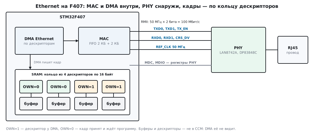
Inside the F407 there is a MAC with its own DMA and 2 KB FIFOs for receive and transmit. Outside is the PHY: a chip such as the LAN8742A or DP83848C that turns bits into signals on the wire and back. Two buses run between them:
- data: RMII — TXD0, TXD1, TX_EN, RXD0, RXD1, CRS_DV and REF_CLK; 50 MHz × 2 bits = 100 Mbit/s. MII uses 4 bits at 25 MHz and more pins. Boards almost always use RMII;
- management: MDC and MDIO — a two-wire management bus to the PHY registers, up to 32 PHYs on one bus.
The 50 MHz RMII reference is supplied to the F407 either by the PHY itself with a built-in multiplier or by an external oscillator (RM0090, "RMII clock sources").
106а.2 Start-up order: RMII before the clocks
MII or RMII is selected by bit 23 MII_RMII_SEL of the SYSCFG_PMC register. RM0090 (33.4.4) requires setting it while the Ethernet controller is in reset or before its clocks are enabled. Then come the MAC clocks and a software reset of the DMA:
void eth_rmii_start(void)
{
    RCC->APB2ENR |= RCC_APB2ENR_SYSCFGEN;
    SYSCFG->PMC  |= SYSCFG_PMC_MII_RMII_SEL;        /* RMII — до включения тактов MAC */
    RCC->AHB1ENR |= RCC_AHB1ENR_ETHMACEN | RCC_AHB1ENR_ETHMACTXEN | RCC_AHB1ENR_ETHMACRXEN;
    ETH->DMABMR  |= ETH_DMABMR_SR;
    while (ETH->DMABMR & ETH_DMABMR_SR) {           /* без 50 МГц от PHY на REF_CLK здесь зависнет */
    }
}
The SR bit clears itself when the reset has completed in all clock domains
of the core. Part of the MAC logic is clocked from REF_CLK (RM0090, figure 358): if
the PHY does not provide 50 MHz — it is unpowered, held in reset, has the wrong crystal — the loop never ends.
The pack driver does the same in the same order: SYSCFG->PMC
before the clocks.
106а.3 PHY over MDIO: who is there and is a cable plugged in
A PHY register is read through MACMIIAR and MACMIIDR: the PHY address (5 bits), the register number (5 bits), the MDC divider and the MB "busy" bit:
uint16_t mdio_read(uint32_t phy, uint32_t reg)
{
    ETH->MACMIIAR = ETH_MACMIIAR_CR_Div102 | (phy << ETH_MACMIIAR_PA_Pos)
                  | (reg << ETH_MACMIIAR_MR_Pos) | ETH_MACMIIAR_MB;
    while (ETH->MACMIIAR & ETH_MACMIIAR_MB) {       /* 64 такта MDC — около 39 мкс */
    }
    return (uint16_t)ETH->MACMIIDR;
}
MDC must not exceed 2.5 MHz, and the divider is chosen by the HCLK frequency (RM0090, table 187):
| HCLK | Divider | MDC |
|---|---|---|
| 168 MHz | /102 | 1.647 MHz |
| 120 MHz | /62 | 1.935 MHz |
| 84 MHz | /42 | 2.000 MHz |
| 48 MHz | /26 | 1.846 MHz |
An MDIO frame is 64 bits: 32 preamble ones, start, operation code, PHY address, register number, 2 turnaround clocks and 16 data bits. At 168 MHz one register read takes 38.9 µs. Polling the PHY in an interrupt every millisecond is not a good idea; once every 100–500 ms is enough.
The first registers are the same in every PHY (the IEEE 802.3 standard), and the drivers from the pack name them like this:
| Register | What it holds |
|---|---|
| 0 BCR | reset (bit 15), auto-negotiation (bit 12), manual speed and duplex |
| 1 BSR | link up (bit 2), auto-negotiation complete (bit 5), PHY capabilities |
| 2, 3 PHYIDR | manufacturer and model identifier |
The LAN8742A answers 0x0007 and 0xC130, the DP83848C 0x2000 and 0x5C90. The
LAN8742A driver compares the second register with the mask 0xFFF0: the low four
bits hold the chip revision, which differs between batches. An "as is"
comparison will break on the next batch.
The auto-negotiation result — speed and duplex — sits in a register of its own in each PHY (in the LAN8742A it is 31, with the "10 Mbit/s" and "full duplex" bits). It is copied into MACCR (bits FES and DM): the MAC does not find this out by itself.
106а.4 Descriptors: how frames get into memory
The Ethernet DMA does not work with "address and length" registers like the DMA in section 9: it walks a list of descriptors in RAM. A normal descriptor is four words, 16 bytes (RM0090, 33.6.7 and 33.6.8):
- word 0 is the status; bit 31 is OWN: 1 — the descriptor belongs to the DMA, 0 — to the program; for a received frame bits 29:16 hold the length (FL);
- word 1 is the buffer size (RBS1, a multiple of 4) and flags, including RCH: the fourth word is the address of the next descriptor;
- word 2 is the buffer address;
- word 3 is the next descriptor.
The program prepares a ring, hands each descriptor to the DMA (OWN = 1) and writes the address of the first one to DMARDLAR. From then on the DMA itself places each frame into the next buffer, writes the length and clears OWN — the frame now belongs to the program. Once the program has processed it, it sets OWN again.
void eth_rx_ring_init(void)
{
    for (uint32_t i = 0; i < NRX; i++) {
        rx_ring[i].buf  = (uint8_t *)rx_buf[i];
        rx_ring[i].des1 = RCH | BUF_SIZE;
        rx_ring[i].next = &rx_ring[(i + 1) % NRX];
        rx_ring[i].des0 = OWN;                      /* отдать DMA — последним */
    }
    ETH->DMARDLAR = (uint32_t)&rx_ring[0];
}
OWN is written last: while it is 0, the DMA will not touch the descriptor, even if the other fields are not ready yet. armclang extracts the frame length with a single bit-field extract instruction, and checks OWN by a signed comparison of the word (bit 31 is the sign bit):
eth_rx_len:  LDR   r1,[r0,#0]
             UBFX  r0,r1,#16,#14
             CMP   r1,#0
             IT    MI
             MOVMI r0,#0
If you enable hardware checksum calculation (the IPCO bit in MACCR) or timestamps, you need enhanced descriptors — 32 bytes, eight words (the EDFE bit in DMABMR). The pack driver enables checksum offload by default and therefore uses enhanced ones.
106а.5 How much memory and how much time
The EMAC_STM32F4xx.c driver: 4 receive buffers and 2 transmit buffers of 1536 bytes —
6144 + 3072 = 9216 bytes; 6 descriptors — 96 bytes normal or 192
enhanced.
How long the program may leave reception unprocessed before the ring of 4 buffers overflows (100 Mbit/s, 80 ns per byte; frame counts are in section 105):
| Traffic | One frame | 4 buffers fill in |
|---|---|---|
| the shortest frames (84 byte times) | 6.72 µs | 26.88 µs |
| the longest (1538) | 123.04 µs | 492.16 µs |
A stream of short frames — a broadcast storm on the network — will overflow the ring faster than one interrupt with the stack completes. The DMA hits a descriptor still owned by the program, sets the RBUS flag ("receive buffer unavailable") and suspends reception: frames are lost, but memory is intact. More buffers give more margin; fewer broadcast frames come from the MAC address filter.
106а.6 The stack on top: what to use
The MAC and PHY driver only handles frames. IP, ARP, TCP and DHCP (sections 105–107) are done by a stack in the firmware:
- lwIP — CubeMX adds it together with the HAL driver
stm32f4xx_hal_eth; - MDK Network in the Keil pack — on top of the CMSIS driver
EMAC_STM32F4xx.cand a PHY driver; for the MCBSTM32F400 board the pack has ready-made examples of an HTTP server, Telnet, FTP, SMTP and SNMP; - if you only need TCP and have no memory for a stack — W5500 over SPI (section 37): the stack is in the chip, and the F103 has no MAC at all.
106а.7 Pitfalls
- RMII selected after the clocks. The MII_RMII_SEL bit is set after the MAC clocks are enabled — the controller stays in MII. SYSCFG_PMC first, then RCC.
- The DMA reset hangs. No 50 MHz on REF_CLK: the PHY is in reset, not powered, has the wrong crystal or mode. The SR bit will never clear — add a timeout and check the clock with an oscilloscope.
- Buffers in CCM. CCM (64 KB at 0x1000 0000) is accessible only to the CPU: the Ethernet DMA cannot see it (RM0090, 2.1 and 2.3.1). Put descriptors and buffers in SRAM1 or SRAM2.
- Normal descriptors with IPCO enabled. Checksum offload requires enhanced descriptors: with normal ones the word layout is not what the DMA expects.
- OWN before the fields. The descriptor is handed to the DMA before the buffer address is written — the frame goes to random memory.
- The PHY identifier is compared in full. The low 4 bits of the second
register are the revision; a comparison without the mask
0xFFF0breaks on a new batch. - The speed is not copied into the MAC. The PHY negotiated 10 Mbit/s or half duplex, while MACCR stayed at 100 Mbit/s and full duplex — frames get through, but with errors and retransmissions.
106а.8 Summary
- The MAC with DMA is inside the F407, the PHY outside; between them RMII (50 MHz × 2 bits) and the MDC/MDIO management bus.
- MII_RMII_SEL goes before the MAC clocks; the DMA reset will not finish without 50 MHz from the PHY.
- MDC no higher than 2.5 MHz: at HCLK 168 MHz the divider /102 gives 1.647 MHz, 38.9 µs per PHY register.
- Frames go through a ring of 16-byte descriptors (32 with IPCO); the OWN bit decides who owns a descriptor.
- The pack driver: 9216 bytes of buffers; 4 buffers of short frames fill in 26.88 µs.
- Buffers and descriptors must not be in CCM: the DMA cannot see it.
Full source code
eth106a.c — Ethernet on the F407 at register level: RMII, reading the PHY over MDIO, the receive descriptor ring.
/* 106а: Ethernet F407 по регистрам — RMII, чтение PHY по MDIO, кольцо дескрипторов приёма.
   Собирается armclang: -DSTM32F407xx. */
#include <stddef.h>
#include <stdint.h>

/* обычный дескриптор DMA — четыре слова (RM0090, 33.6.7 и 33.6.8) */
typedef struct eth_desc {
    volatile uint32_t des0;             /* бит 31 OWN: 1 — дескриптор у DMA */
    uint32_t des1;                      /* размер буфера и флаги */
    uint8_t *buf;                       /* адрес буфера */
    struct eth_desc *next;              /* следующий дескриптор (режим цепочки) */
} eth_desc_t;

_Static_assert(sizeof(eth_desc_t) == 16, "обычный дескриптор — 16 байт");
_Static_assert(SYSCFG_PMC_MII_RMII_SEL == (1u << 23), "MII_RMII_SEL — бит 23 SYSCFG_PMC");
_Static_assert(ETH_MACMIIAR_CR_Div102 == (4u << ETH_MACMIIAR_CR_Pos), "CR = 100: HCLK/102");

#define OWN      (1u << 31)
#define RCH      (1u << 14)             /* RDES1: next — адрес следующего дескриптора */
#define NRX      4u
#define BUF_SIZE 1536u                  /* кратно 4: RBS1 обязан быть кратен ширине шины */

static eth_desc_t rx_ring[NRX];
static uint32_t rx_buf[NRX][BUF_SIZE / 4];          /* в SRAM1/SRAM2, не в CCM: DMA её не видит */

void eth_rmii_start(void)
{
    RCC->APB2ENR |= RCC_APB2ENR_SYSCFGEN;
    SYSCFG->PMC  |= SYSCFG_PMC_MII_RMII_SEL;        /* RMII — до включения тактов MAC */
    RCC->AHB1ENR |= RCC_AHB1ENR_ETHMACEN | RCC_AHB1ENR_ETHMACTXEN | RCC_AHB1ENR_ETHMACRXEN;
    ETH->DMABMR  |= ETH_DMABMR_SR;
    while (ETH->DMABMR & ETH_DMABMR_SR) {           /* без 50 МГц от PHY на REF_CLK здесь зависнет */
    }
}

uint16_t mdio_read(uint32_t phy, uint32_t reg)
{
    ETH->MACMIIAR = ETH_MACMIIAR_CR_Div102 | (phy << ETH_MACMIIAR_PA_Pos)
                  | (reg << ETH_MACMIIAR_MR_Pos) | ETH_MACMIIAR_MB;
    while (ETH->MACMIIAR & ETH_MACMIIAR_MB) {       /* 64 такта MDC — около 39 мкс */
    }
    return (uint16_t)ETH->MACMIIDR;
}

int phy_is_lan8742a(uint32_t phy)
{
    return mdio_read(phy, 2) == 0x0007 && (mdio_read(phy, 3) & 0xFFF0u) == 0xC130;
}

void eth_rx_ring_init(void)
{
    for (uint32_t i = 0; i < NRX; i++) {
        rx_ring[i].buf  = (uint8_t *)rx_buf[i];
        rx_ring[i].des1 = RCH | BUF_SIZE;
        rx_ring[i].next = &rx_ring[(i + 1) % NRX];
        rx_ring[i].des0 = OWN;                      /* отдать DMA — последним */
    }
    ETH->DMARDLAR = (uint32_t)&rx_ring[0];
}

/* длина принятого кадра — поле FL (RDES0[29:16]); 0, если дескриптор ещё у DMA */
uint32_t eth_rx_len(const eth_desc_t *d)
{
    uint32_t s = d->des0;
    return (s & OWN) ? 0u : (s >> 16) & 0x3FFFu;
}
Next: section 106б "A packet byte by byte: Ethernet, ARP, IPv4, ICMP, UDP and TCP as a microcontroller sees them" — the same frames taken apart down to the byte: ARP, ping, UDP and a TCP reset with your own code.