 Embedded HandbookApps
Appendix B. CMSIS cheat sheet
Everything from CMSIS that you need when you work with registers directly, on one page. This is not a peripheral library: CMSIS gives you access to the Cortex‑M core (interrupts, the system timer, masks, barriers, bit operations) and register access macros. You configure the peripherals yourself, with registers from the family header (appendix A).
Every name here is called in a test file and built for Cortex‑M3.
B.1 Register access
Macros from the family header (stm32f10x.h, stm32f4xx.h).
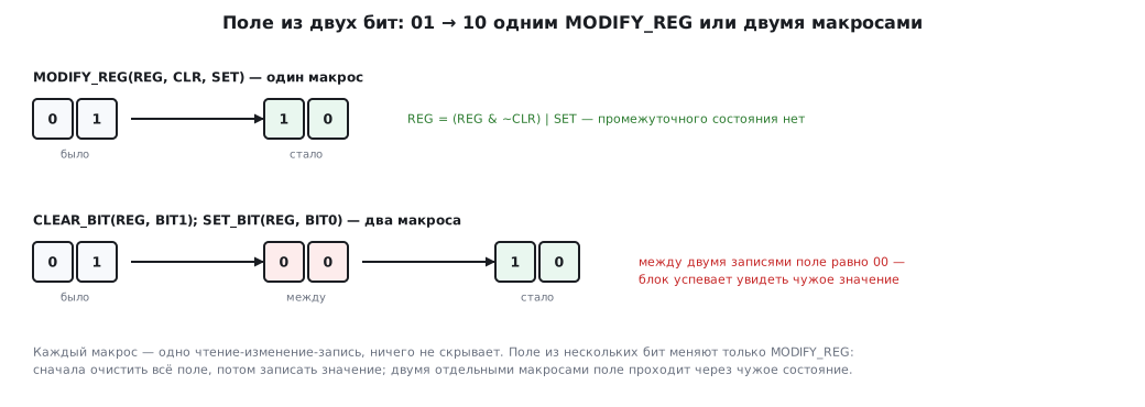
They hide nothing: SET_BIT, CLEAR_BIT and MODIFY_REG expand into one read-modify-write operation,
the others into one read or one write.
| Macro | What it does | Equivalent |
|---|---|---|
SET_BIT(REG, BIT) |
set | REG \|= BIT |
CLEAR_BIT(REG, BIT) |
clear | REG &= ~BIT |
READ_BIT(REG, BIT) |
read; not 0/1, but a mask | REG & BIT |
CLEAR_REG(REG) |
zero the register | REG = 0 |
WRITE_REG(REG, VAL) |
write the whole register | REG = VAL |
READ_REG(REG) |
read the whole register | REG |
MODIFY_REG(REG, CLR, SET) |
clear a mask, set bits | REG = (REG & ~CLR) \| SET |
⚠️
READ_BITreturns a mask, not a boolean value.READ_BIT(x, BIT5) == 1is true only for bit zero (section 8). Compare with zero:READ_BIT(x, BIT5) != 0.⚠️ Read-modify-write macros are not suitable for flag registers.
SET_BIT(EXTI->PR, EXTI_PR_PR0)writes back all the ones it has read, and so clears all the pending lines along the way.CLEAR_BIT(TIM2->SR, TIM_SR_UIF)also writes zero into a flag that got set between the read and the write, and the event is lost. Flags are cleared with a direct write:EXTI->PR = EXTI_PR_PR0,TIM2->SR = ~TIM_SR_UIF(sections 7 and 13).
MODIFY_REG is the only correct way to change a field of several
bits: first clear the whole field, then write the value. Two separate
SET_BIT/CLEAR_BIT calls leave an intermediate state.
B.2 Interrupts: NVIC
| Function | What it does |
|---|---|
NVIC_SetPriorityGrouping(g) |
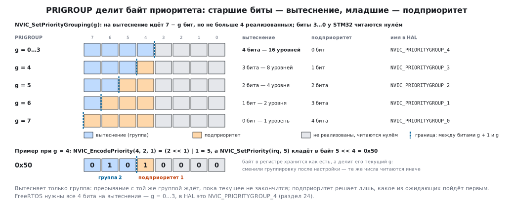
where the priority is split (the PRIGROUP field): 7 − g bits go to preemption, but no more than are implemented. On STM32, with g = 0…3 all 4 bits are preemption, as FreeRTOS needs (section 24); with g = 7, none. In HAL the digit in the name is the number of preemption bits: NVIC_PRIORITYGROUP_4 = 3 |
NVIC_GetPriorityGrouping() |
current grouping |
NVIC_EnableIRQ(irq) / NVIC_DisableIRQ(irq) |
enable / disable |
NVIC_GetEnableIRQ(irq) |
whether it is enabled |
NVIC_SetPendingIRQ(irq) / NVIC_ClearPendingIRQ(irq) |
set / clear pending |
NVIC_GetPendingIRQ(irq) |
whether it is pending |
NVIC_GetActive(irq) |
whether it is being serviced now |
NVIC_SetPriority(irq, p) |
logical priority: 0 is the highest, 15 the lowest |
NVIC_GetPriority(irq) |
read the logical priority |
NVIC_EncodePriority(g, pre, sub) |
build from preemption priority and subpriority |
NVIC_SystemReset() |
software reset; does not return |
The logical priority p goes into the register as p << 4: STM32
has four significant bits out of eight. NVIC_SetPriority(irq, 5) is 0x50
in the register, the very FreeRTOS threshold (section 28).
The order of configuration: grouping → priority → enable.
The default priority is 0, the highest; under a kernel this is a mistake.
irq comes from the IRQn_Type enumeration in the family header: USART1_IRQn,
EXTI0_IRQn, TIM2_IRQn… System exceptions are there too, with negative
numbers: SysTick_IRQn = −1, PendSV_IRQn = −2, SVCall_IRQn = −5.
B.3 Global masking
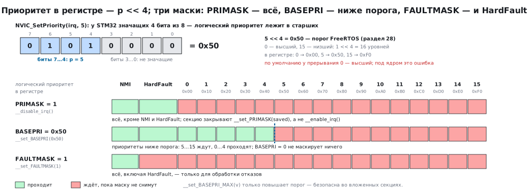
Three mask registers, three levels of strictness:
| Register | Functions | Masks |
|---|---|---|
PRIMASK |
__disable_irq() / __enable_irq(), __get_PRIMASK() / __set_PRIMASK(v) |
everything except NMI and HardFault |
BASEPRI |
__get_BASEPRI() / __set_BASEPRI(v) / __set_BASEPRI_MAX(v) |
priorities equal to the threshold and lower (numerically ≥ v); v is the register value, that is, the priority shifted into the upper 4 bits (5 → 0x50); 0 masks nothing |
FAULTMASK |
__get_FAULTMASK() / __set_FAULTMASK(v) |
everything, including HardFault; only for fault handling |
__set_BASEPRI_MAX(v) can only raise the threshold, not lower it:
it is safe in nested sections. FreeRTOS sets BASEPRI = 0x50
while it works with its lists (section 28).
A correct critical section without a kernel restores the previous value instead of enabling unconditionally:
uint32_t saved = __get_PRIMASK();
__disable_irq();
/* ... */
__set_PRIMASK(saved);       /* а не __enable_irq(): секция могла быть вложенной */
Other core registers: __get_IPSR() is the number of the active exception
(0 means thread mode: this is how you check "am I in an interrupt?"); __get_MSP() /
__get_PSP() and the matching set functions are the two stack pointers (section 23);
__get_CONTROL() / __set_CONTROL(v) are privileges and stack selection.
B.4 System timer
| Function | What it does |
|---|---|
SysTick_Config(ticks) |
start with a period of ticks clock cycles, interrupt enabled, lowest priority; returns 0 on success |
SystemCoreClockUpdate() |
recalculate SystemCoreClock from the RCC registers |
SystemCoreClock |
variable: the core frequency in hertz, what you wrote, not what you measured |
SysTick_Config(SystemCoreClock / 1000) gives a 1 ms tick. The argument is a number
of clock cycles, 24 bits wide: at 72 MHz nothing slower than 4 Hz is possible (section 33).
⚠️
SystemCoreClockis correct only ifSystemCoreClockUpdate()was called after configuring RCC, or the frequency was set by the standardSystemInit. If you raised the clock by hand and did not update it, every calculation based on it is wrong.
B.5 Sleep and barriers
| Function | What it does |
|---|---|
__WFI() |
wait for interrupt: Sleep mode until any interrupt |
__WFE() |
wait for event: the same, but also wakes on a SEV event |
__SEV() |
send an event |
__NOP() |
nothing; for code alignment and as a place for a breakpoint. The timing is not guaranteed, the core may drop a NOP from the pipeline; short delays are counted with DWT->CYCCNT or a timer (section 13) |
__DSB() |
data barrier: wait until all memory accesses complete |
__ISB() |
instruction barrier: flush the pipeline |
__DMB() |
memory access ordering barrier |
When barriers are mandatory: after writing registers that change the behavior
of the core or memory, such as SCB->VTOR, BASEPRI, enabling the MPU, switching the
vector table, entering sleep. The typical pair before __WFI():
__DSB(); __ISB();. FreeRTOS calls them itself in critical sections.
B.6 Bit operations
One instruction each, faster than any loop in C.
| Function | What it does | Example |
|---|---|---|
__REV(x) |
reverse the bytes of a word | 0x12345678 → 0x78563412 |
__REV16(x) |
bytes in each halfword | network order for uint16_t |
__REVSH(x) |
signed halfword | |
__RBIT(x) |
reverse the bits | 1 → 0x80000000 |
__CLZ(x) |
count leading zeros | __CLZ(1) = 31; number of the highest set bit = 31 − __CLZ(x) |
__ROR(x, n) |
rotate right | |
__SSAT(x, n) / __USAT(x, n) |
saturate to n bits, signed / unsigned |
no overflow |
__REV is what you need for network byte order (section 37) and for
protocols with reversed byte order. __CLZ is a fast search for the highest bit:
this is exactly how the FreeRTOS priority scheduler finds a ready task.
B.7 Exclusive access
Atomicity on Cortex‑M3 without disabling interrupts:
do {
    v = __LDREXW(&counter);             /* прочитать с меткой */
} while (__STREXW(v + 1, &counter));    /* записать, если никто не вмешался */
__STREXW returns 0 on success and 1 if there was an interrupt or another
write between the read and the write; then you retry. This is how an
atomic increment (section 30) is done without a critical section. The variants
for halfword and byte are __LDREXH/__STREXH, __LDREXB/__STREXB;
__CLREX() clears the tag.
Cortex‑M0 does not have these instructions; there you only have masking.
B.8 Bit-banding
These are not CMSIS functions but a property of the Cortex‑M3/M4 address space (section 1): each bit of the first megabyte of SRAM and of the peripherals has a matching word in the alias region.
#define BITBAND_PERI(addr, bit)  (0x42000000u + (((addr) - 0x40000000u) * 32u) + ((bit) * 4u))
#define PC13_ODR  (*(volatile uint32_t *)BITBAND_PERI(0x4001100Cu, 13))

PC13_ODR = 0;      /* атомарная запись одного бита без чтения регистра */
On F1, GPIOC->ODR is at address 0x4001100C (the port C base is
0x40011000), and its bit 13 is address 0x422201B4, as in section 1.
It is safer not to type the constant by hand but to take it from the header,
(uint32_t)&GPIOC->ODR: 0x40010C0C is already GPIOB->ODR, and such a
macro would silently control PB13. A write to the alias
is atomic and does not touch neighboring bits, which ODR |= … cannot give you.
Cortex‑M0 and M7 do not have this region.
B.9 What to remember
READ_BITreturns a mask,MODIFY_REGis the only way to change a field.- Logical priority
p→ registerp << 4; the order: grouping, priority, enable. PRIMASKmasks everything;BASEPRIthe threshold and everything below;__set_BASEPRI_MAXonly raises it.- A section without a kernel restores
PRIMASKand does not enable unconditionally. SysTick_Configreturns 0 on success;SystemCoreClockis what was written, not measured.- Before
__WFI():__DSB(); __ISB(). __REVfor network order,__CLZfor the highest bit.__LDREXW/__STREXWgive atomicity without disabling interrupts, except on M0.