 Embedded HandbookApps
5. Three levels of abstraction: CMSIS, HAL and LL
The same line "turn on the LED" can be written in four ways. The argument about which one is right is usually a matter of taste — yet it is settled simply: look at what each way turns into after the compiler. That is what we will do.
Terms used in the documentation
Term Meaning CMSIS (Cortex Microcontroller Software Interface Standard) a standard for names and headers for Cortex-M cores HAL (Hardware Abstraction Layer) a library on the "one function — one action" level LL (Low Layer) thin inline functions over the registers SPL (Standard Peripheral Library) the earlier ST library, before HAL code generator the program that generates the project code (CubeMX) user code section a user block that the generator preserves MSP (MCU support package) clock and pin setup for a peripheral block weak symbol ( __weak)a weak definition: an ordinary one with the same name replaces it callback a function the library calls back on an event linker map the map file produced by the linker
5.1 Who invented what
| Layer | Author | What it is |
|---|---|---|
| CMSIS | ARM | a standard: a description of the core, the registers, common names. Not a library but a convention |
| CMSIS Device | ST | headers with the register map of a specific chip: stm32f10x.h, stm32f4xx.h |
| SPL | ST | the old peripheral library. No longer developed, found in old projects |
| HAL | ST | today's library: a single interface over all families |
| LL | ST | thin wrappers over the registers, with almost no overhead |
In practice it looks like this: CMSIS gives the names (GPIOA, RCC_APB2ENR_IOPCEN),
LL gives short functions over the same registers, HAL gives ready-made procedures
with checks, timeouts and error handling.
Important: CMSIS is not an alternative to HAL. The CMSIS headers are always included — HAL and LL themselves rely on them.
5.2 CMSIS and HAL macros
The family header declares a small set of macros for working with registers. There is no magic in them — here are their full definitions:
#define SET_BIT(REG, BIT)     ((REG) |= (BIT))
#define CLEAR_BIT(REG, BIT)   ((REG) &= ~(BIT))
#define READ_BIT(REG, BIT)    ((REG) & (BIT))
#define CLEAR_REG(REG)        ((REG) = (0x0))
#define WRITE_REG(REG, VAL)   ((REG) = (VAL))
#define READ_REG(REG)         ((REG))
#define MODIFY_REG(REG, CLEARMASK, SETMASK)  \
        WRITE_REG((REG), (((READ_REG(REG)) & (~(CLEARMASK))) | (SETMASK)))
All they do is save you from typos in bit operations and make the code
readable. MODIFY_REG is more useful than the rest: it performs the correct
sequence "clear the field → put the value", which is easy to get wrong
by hand.
/* одно и то же */
RCC->CFGR = (RCC->CFGR & ~RCC_CFGR_PLLMULL) | RCC_CFGR_PLLMULL9;
MODIFY_REG(RCC->CFGR, RCC_CFGR_PLLMULL, RCC_CFGR_PLLMULL9);
⚠️
READ_BITreturns a mask, not a one — more on this in sections 3 and 8. Compare the result with zero.
HAL macros. HAL has its own set, and a much larger one: the F4 library declares
1410 macros with the prefix __HAL_. They are not functions — they are the same
register accesses hidden behind a clear name.
| Group | Example | What is inside |
|---|---|---|
| enable a block's clock | __HAL_RCC_GPIOA_CLK_ENABLE() |
a bit in RCC->AHB1ENR; there are 89 such macros |
| a block's interrupts and flags | __HAL_UART_ENABLE_IT(&huart1, UART_IT_RXNE) |
a bit in CR1, CR2 or CR3 |
| a small change on the fly | __HAL_TIM_SET_COMPARE(&htim3, TIM_CHANNEL_1, 500) |
a write to CCR1, bypassing the channel setup |
Next — three places where these macros behave differently from what the reader expects.
Enabling the clock reads the register back. The full definition:
#define __HAL_RCC_GPIOA_CLK_ENABLE()   do { \
    __IO uint32_t tmpreg = 0x00U; \
    SET_BIT(RCC->AHB1ENR, RCC_AHB1ENR_GPIOAEN); \
    /* Delay after an RCC peripheral clock enabling */ \
    tmpreg = READ_BIT(RCC->AHB1ENR, RCC_AHB1ENR_GPIOAEN); \
    UNUSED(tmpreg); \
  } while(0U)
The read here is not a check. A write to RCC travels over the bus and does not reach the block
instantly; an access to a register of the port itself, issued as the next instruction,
may arrive before the clock is on — and be lost. Reading the same bit
forces the core to wait for the bus response. Your own code of the form "RCC->AHB1ENR |= …;
and immediately GPIOA->MODER = …" hits exactly this: the port gets configured every other time and
differently depending on the optimisation level. The cure is the same read-back.
A macro can return from the function. __HAL_LOCK is the latch that
starts almost every HAL function:
#define __HAL_LOCK(__HANDLE__)                 \
    do {                                       \
        if ((__HANDLE__)->Lock == HAL_LOCKED)  \
        {                                      \
           return HAL_BUSY;                    \
        }                                      \
        else                                   \
        {                                      \
           (__HANDLE__)->Lock = HAL_LOCKED;    \
        }                                      \
      } while (0U)
The return sits inside the macro. In your own function that returns void,
armclang will not build the line __HAL_LOCK(&huart1);, while GCC 12 will build it with a single
warning, and the function will silently exit. In a function with another return type
it will build and return the wrong thing. The macro is meant only for HAL functions
that return HAL_StatusTypeDef, and it is not a mutex: checking and
setting Lock are two separate operations, and an interrupt can come between them.
The argument is expanded several times. __HAL_UART_ENABLE_IT is a chain
of conditional expressions: the upper four bits of a UART_IT_* constant hold the register
number, and the macro uses it to choose between CR1, CR2 and CR3. The parameter
is substituted into the text three times, so an expression with a side effect —
__HAL_UART_ENABLE_IT(&h, mask[i++]) — will take effect more than once. The rule is general
for any macro: only simple values as arguments.
5.3 Atomic versions
The headers of most families declare atomic variants alongside. On F4 they look like this:
#define ATOMIC_SET_BIT(REG, BIT)                             \
  do {                                                       \
    uint32_t val;                                            \
    do {                                                     \
      val = __LDREXW((__IO uint32_t *)&(REG)) | (BIT);       \
    } while ((__STREXW(val,(__IO uint32_t *)&(REG))) != 0U); \
  } while(0)
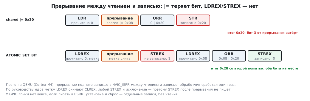
This works on the pair of instructions LDREX/STREX: the first reads the value
and sets a "tag", the second writes only if the tag is intact. The tag is cleared by
any exception, by CLREX and by another STREX; if it has been cleared, the loop repeats.
The result is a register change that will not be lost because of an interrupt
in the middle. But a write by DMA, or a bit that the peripheral itself changed
between the read and the write, does not clear the tag: these instructions do not protect against them.
Families on Cortex-M0/M0+ (F0, G0, C0, L0) have no LDREX/STREX instructions, and the
same macros are made differently there: for the duration of the write they mask interrupts
through PRIMASK.
There are ATOMIC_SET_BIT, ATOMIC_CLEAR_BIT, ATOMIC_MODIFY_REG and their 16-bit
variants.
⚠️ The old F1 headers have no atomic macros. If a shared register is changed both from the main code and from an interrupt, on F1 you will have either to enter a critical section or to use registers with separate set and reset — such as
BSRRof GPIO, which is immune to the race by design.
An experiment in QEMU (_verify/rmw5/): the main code sets bit 5, the interrupt sets bit 3, and the interrupt
is raised exactly between the read and the write. A plain |= leaves 0x20 — the interrupt's bit
is overwritten; LDREX/STREX on the second attempt gives 0x28. According to the core manual, the
LDREX tag is cleared by any exception — that is why the first STREX after the interrupt does not write.
5.4 "= or |=?"
The most frequent beginner's question. The right answer depends on the register, and the cost of a mistake differs.
|= (read-modify-write) — when the register holds other bits that
must be kept. Almost everything is configured this way: RCC->APB2ENR, GPIOx->CRL, TIMx->CR1.
RCC->APB2ENR |= RCC_APB2ENR_IOPCEN;   /* включили порт C, не тронув остальные */
RCC->APB2ENR  = RCC_APB2ENR_IOPCEN;   /* включили порт C, ВЫКЛЮЧИЛИ всё прочее */
The second line is the classic cause of "UART was working, I added a port — UART died".
= (a plain write) — when the register keeps no state between writes.
The main example is BSRR of GPIO: it is write-only, reading returns zeros,
and every write stands on its own.
GPIOC->BSRR = GPIO_BSRR_BS13;    /* правильно */
GPIOC->BSRR |= GPIO_BSRR_BS13;   /* работает, но делает лишнее чтение шины */
How "extra" it is can be seen in the next section, where it is measured.
The rule. If a register holds configuration — read, modify, write
(|=, &=, MODIFY_REG). If a register is a pure command register, with no stored
settings (BSRR, BRR, EXTI->PR, DMA1->IFCR), — write the mask directly.
A start bit that lies next to settings is set with |=: SWSTART
in ADC_CR2 on F1 and F4 sits next to ADON, CONT and DMA, and
ADC1->CR2 = ADC_CR2_SWSTART will switch the ADC off. Flags that are cleared
by writing zero (TIMx->SR) are cleared by writing the inverted mask:
TIM2->SR = ~TIM_SR_UIF; — a zero only into its own bit, the ones in the others
change nothing. An &= operation here may erase a flag that the hardware
raises between the read and the write.
5.5 What each level turns into
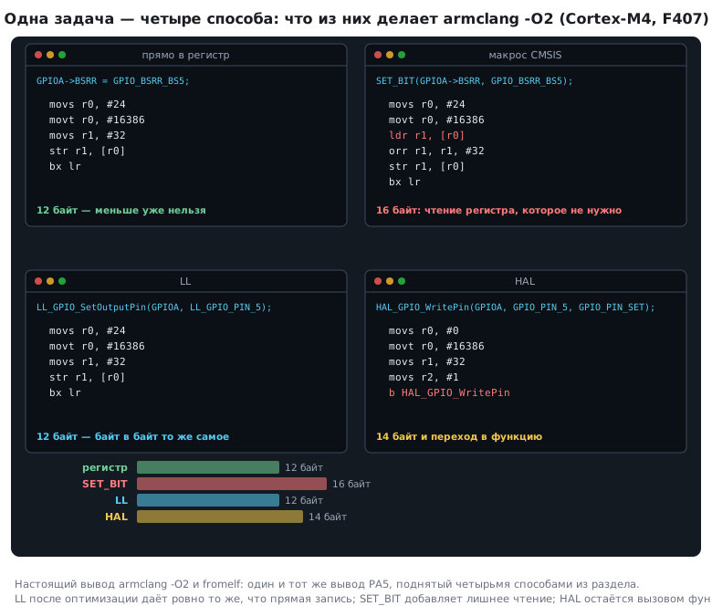
Take one task — set pin PA5 — and write it in four ways.
Compile with -O2 for Cortex-M4 and look at what we get.
The register directly:
GPIOA->BSRR = GPIO_BSRR_BS5;
movs    r0, #24
movt    r0, #16386        @ адрес GPIOA->BSRR
movs    r1, #32           @ маска бита 5
str     r1, [r0]          @ одна запись
bx      lr
A CMSIS macro:
SET_BIT(GPIOA->BSRR, GPIO_BSRR_BS5);
movs    r0, #24
movt    r0, #16386
ldr     r1, [r0]          @ ЛИШНЕЕ чтение
orr     r1, r1, #32
str     r1, [r0]
bx      lr
LL:
LL_GPIO_SetOutputPin(GPIOA, LL_GPIO_PIN_5);
movs    r0, #24
movt    r0, #16386
movs    r1, #32
str     r1, [r0]          @ ровно то же, что и напрямую
bx      lr
HAL:
HAL_GPIO_WritePin(GPIOA, GPIO_PIN_5, GPIO_PIN_SET);
movs    r0, #0
movt    r0, #16386        @ адрес GPIOA
movs    r1, #32           @ номер вывода
movs    r2, #1            @ состояние
b       HAL_GPIO_WritePin @ переход в функцию, которая ещё разбирает аргументы
The conclusions that follow from this:
- LL costs nothing. Its functions are declared
static inlineand after optimisation give the same code as a direct register write. Readability is free. SET_BITonBSRRis worse than a direct write. The macro expands into|=, and therefore adds a read of a register that makes no sense to read. For configuration registersSET_BITis fine, for command registers it is not.- HAL is a real function call, and inside it there is also argument checking and branching. For blinking an LED the difference is imperceptible, but in an interrupt handler that fires tens of thousands of times per second it becomes noticeable.
5.6 What to choose
| Task | Level |
|---|---|
| learning, understanding the hardware | registers |
| hot code: handlers, bottlenecks | registers or LL |
| ordinary peripherals in a production project | LL or HAL |
| USB, a file system, Ethernet, graphics | HAL and ready-made stacks — writing these from scratch does not pay off |
| moving a project between STM32 families | HAL |
Mixing levels is allowed and normal: configure the peripherals with CubeMX
and HAL, and inside a critical interrupt poke BSRR directly. This is not "dirty
code" but ordinary engineering practice.
A small caveat about HAL portability. The single interface really does let you move code between F4 and L4 with little effort, but the promise does not hold completely: the families have different sets of peripherals, and functions such as
HAL_GPIO_Inittake structures with different fields (F1, for example, has noAlternatefield). Porting becomes easier, but not free.
5.7 A project generated by CubeMX
CubeMX — a separate program, built into CubeIDE versions 1.x, — generates
a ready project from the pin layout and the
settings. Let us take apart a real one: the example for a board with an
STM32F407 that ships in the Keil pack. All its files are built with armclang.
| File | What is in it |
|---|---|
*.ioc |
all CubeMX settings as "key=value" text: chip, pins, NVIC, project parameters |
Src/main.c |
main, SystemClock_Config, the MX_*_Init functions, Error_Handler |
Src/stm32f4xx_it.c |
interrupt and exception handlers |
Src/stm32f4xx_hal_msp.c |
HAL_MspInit and HAL_<block>_MspInit: clocks and pins for the peripherals |
Inc/stm32f4xx_hal_conf.h |
which HAL modules are enabled, the crystal frequency HSE_VALUE |
startup_*.s, system_stm32f4xx.c |
the vector table, the code before main, SystemCoreClock (section 11.2) |
USER CODE blocks. On each generation the file is rewritten entirely,
except for the parts between /* USER CODE BEGIN … */ and /* USER CODE END … */.
The project's main.c has 17 such blocks — from Header to Error_Handler_Debug.
A line outside a block disappears on the next generation without a warning.
Preservation of the blocks is enabled by the setting ProjectManager.KeepUserCode=true in
.ioc. It is more convenient to keep your own code in separate files and to leave
only calls in the blocks of main.c.
Start-up order in main: HAL_Init → SystemClock_Config →
MX_GPIO_Init → the endless loop.
HAL_Initenables prefetch and both Flash caches. It sets the NVIC priority grouping — 4, all bits for preemption, — and starts SysTick at 1 ms, still from HSI. At the end it callsHAL_MspInit. It does not touch the Flash latency.SystemClock_Configconfigures the PLL: 25 MHz / 25 × 336 / 2 = 168 MHz, APB1 — 42 MHz, APB2 — 84 MHz. It also sets the Flash latencyFLASH_LATENCY_5throughHAL_RCC_ClockConfig— the "Flash speed" is configured exactly here (section 6).MX_*_Init— the peripherals according to the pin layout; the prefixMXmeans that the function was written by the generator.Error_Handler— HAL comes here if a configuration step failed. By default it is an endless loop; it is replaced with your own reaction — a log entry, a reset through the watchdog (section 12).
In this project's stm32f4xx_it.c there are only six core exceptions:
SysTick, SVC and PendSV were taken here by the operating system. In a project
without one, SysTick_Handler with a call to HAL_IncTick lives right here.
HAL_MspInit enables the SYSCFG and PWR clocks and sets the priorities SVCall 14 and
PendSV 15.
Weak functions and callbacks. HAL declares the event handlers
weak (__weak) and empty: HAL_GPIO_EXTI_Callback,
HAL_UART_RxCpltCallback and others. To get the event, you write in your own file
a function with the same name and the same signature, and the linker
will prefer it. The project itself replaces HAL_GetTick with its own this way — in the
USER CODE 0 block, so that generation does not erase it.
static volatile uint32_t pressed;

void HAL_GPIO_EXTI_Callback(uint16_t GPIO_Pin)
{
    if (GPIO_Pin == GPIO_PIN_2)
        pressed = 1;
}

void handle_press(void);

/* Из главного цикла */
void poll_press(void)
{
    if (pressed) {
        pressed = 0;                    /* сначала сбросить, потом обработать */
        handle_press();
    }
}

/* Цепочка из вектора: EXTI2_IRQHandler → HAL → обратный вызов */
void EXTI2_IRQHandler(void)
{
    HAL_GPIO_EXTI_IRQHandler(GPIO_PIN_2);
}
HAL_GPIO_EXTI_IRQHandler clears the flag in EXTI and only then calls
the callback. Programs clear the flag before handling, not after:
otherwise an event that arrives during handling will be erased. The pin is compared
with the mask GPIO_PIN_2 (0x0004), not with the pin number 2.
An experiment with linking. stm32f4xx_hal_gpio.c from the pack was linked with armlink
with three variants of the handler, and the result was read from the linker map:
| What is in your file | What ended up in the image |
|---|---|
void HAL_GPIO_EXTI_Callback(uint16_t GPIO_Pin) |
our handler; the empty weak HAL function is discarded |
void HAL_GPIO_EXTI_CallBack(uint16_t GPIO_Pin) — one letter wrong |
the empty weak HAL function, 2 bytes — a single return instruction; our handler is discarded as unused |
HAL_GPIO_EXTI_Callback(uint16_t pin) — without void |
does not build: implicit int is forbidden since C99, and the type conflicts with the declaration in HAL |
⚠️ A typo in a callback name is the quietest HAL error. No error, no warning: the interrupt arrives, the flag in EXTI is cleared, and your code is never called. The check is a breakpoint in the handler or a search for your name in the linker map. The
-Wmissing-prototypesswitch also catches such a typo: the correct name has a declaration in the HAL header, the wrong one does not, and the compiler will warn.
5.8 Pitfalls
READ_BIT(...) == 1 is false almost always. The macro returns a mask — compare with zero (5.2).
A bit in a shared register is lost on an interrupt. The F1 headers have no atomic macros: a critical section
or registers with separate set and reset such as BSRR (5.3).
A HAL callback is not called, and there are no errors. A typo in the name: HAL calls the weak stub. The check is a breakpoint in the handler or your name in the linker map (5.7).
5.9 Summary
- CMSIS is not a library but a naming convention; its headers are always included, and both HAL and LL rely on them.
- CMSIS macros are simple wrappers over bit operations.
MODIFY_REGperforms the correct sequence "clear → write". - Atomic versions of the macros on
LDREX/STREX(on F4 and others) protect against interrupts but not against DMA; on F0, G0, C0 and L0 they are made throughPRIMASK, and the old F1 headers do not have them. |=for configuration registers,=for command registers. Writing=instead of|=toRCC->APB2ENRswitches off all the other peripherals.- After optimisation LL gives the same machine code as a direct register write, — readability comes for free.
SET_BITonBSRRadds a pointless read: a direct write is needed there.- HAL is a function call with checks; for initialisation this is unnoticeable, for a hot loop it is significant.
- Levels can be mixed in one project.
- A CubeMX project:
.ioc— settings,main.c— start-up order,*_it.c— handlers,*_msp.c— clocks and pins of the peripherals. Your own code goes only intoUSER CODEblocks. HAL_Initdoes not configure the Flash latency — that is done bySystemClock_Config. HAL callbacks are weak functions, and a typo in the name silently leaves the empty one.
Next: section 5а "HAL in practice" — the handle and its states, three transfer modes, HAL_BUSY, restarting reception in the callback and the HAL_GetTick clock.